Contents
Everything you need to know about Blended Cements
[wpecpp name=”package” price=”75″ align=”center”]
by Michael Schmidt*, Bernhard Middendorf**, Carsten Vellmer†, and Carsten Geisenhanslueke‡
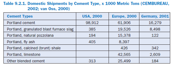
Blended cements enhance the capabilities of cement to be adapted more individually to the requirements of the cement consumer, which vary quite considerably depending on the area of application. In addition, the blended cements make it possible to lower the consumption of natural raw materials, conserve landfill space, and save fuel energy for clinker production. Blended cements are produced by intimately blending or intergrinding inorganic constituents with port-land cement or clinker and gypsum. Frequently, the primary blending materials are ground granu-lated blast-furnace slag, silica fume, pozzolan, fly ash, calcined (burnt) clay, calcined (burnt) shale/slate, limestone, etc., (see Figure 9.2.1). Blended cements of different compositions are well established in Europe. As shown in Table 9.2.1, blended cements accounted for about two-thirds of the total European cement consumption of about 175 million metric tons, in the year 2000 alone. However, the production of blended cements in the United States is not widespread; up to the present, blended cements play only a minor role in the United States.
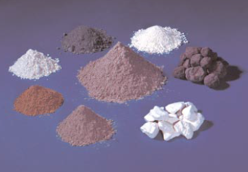
Figure 9.2.1. Blended cement (center) surrounded by (bottom and clockwise) portland cement, fly ash, blast-furnace slag, silica fume, calcined (burnt) clay, clinker and gypsum.
DEFINITIONS AND SPECIFICATIONS
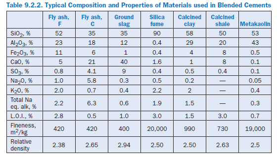
Blended hydraulic cements are produced by blending or intergrinding one or more inorganic materials with portland cement. The primary blending materials, also sometimes termed as supplementary cementitious materials, are blast-furnace slag, silica fume, pozzolan, fly ash, calcined clay, calcined shale/slate, and limestone; their typical chemical composition and selected properties are given in Table 9.2.2.
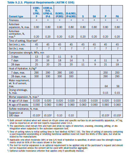
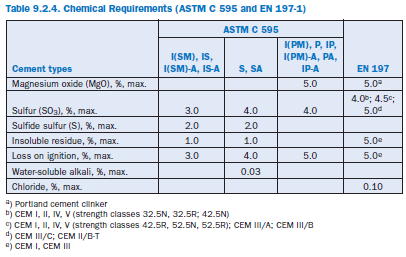
In the U.S., specifications for blended hydraulic cements are covered by ASTM (C 595, C 1157), in Europe by EN (EN 197). ASTM C 595 defines five classes of blended cements and prescribes limiting percentages of constituents in each. Cement types according to ASTM C 595 are Portland blast-furnace slag (Type IS), Portland–pozzolan cement (Type IP, Type P), Pozzolan-modified portland cement (Type I[PM]), Slag-modified portland cement (Type I[SM]) and Slag cement (Type S). These cements may also be designated as air-entraining (suffix A), moderate sulfate resistant (suffix MS), or low or moderate heat of hydration (suffixes LH; MH). Physical and chem-ical requirements for blended cements according to ASTM C 595 and EN 197 are given in Tables 9.2.3 and 9.2.4 respectively.
ASTM C 1157 contains performance requirements for hydraulic cement with no restrictions on the composition of the cement or its constituents. The cements are classified according to their intended use into six types. They include blended hydraulic cement and portland cement for General construction (Type GU), High early strength cement (Type HE), Moderate sulfate resist-ant cement (Type MS), High sulfate resistant cement (Type HS), Moderate heat of hydration cement (Type MH), and Low heat of hydration cement (Type LH). These cements may also be designated for low reactivity with alkali-reactive aggregates (suffix R).
ASTM C 1157 emphasizes the ability of the blended cement to perform and contains no restrictions on the composition of the material.
Therefore, it allows optimal use of ingredients to opti-mize for particular concrete properties. In ASTM C 1157, cement performance is determined by testing autoclave expansion (ASTM C 151), mortar bar expansion (ASTM C 1038), and setting time (ASTM C 191). Default minimum strength requirements of ASTM C 1157 are given in Table 9.2.5.

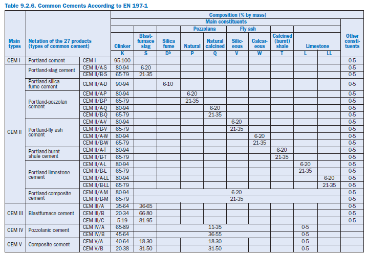
EN 197-1 defines and gives the specifications of 27 distinct common cement products and their constituents. The definition of each cement includes the proportions in which the constituents are combined. The definition also includes requirements the constituents have to meet and the mechanical, physical, and chemical requirements.
Additionally, in Europe, national standards provide the basis for special cements. For example, in Germany standard DIN 1164 gives prescriptive specifications for special cements with low heat of hydration (NW [LH]), high sulfate resistance (HS), and low reactivity with alkali-reactive aggre-gates (NA [R]). They are classified according to testing (NW [LH]), compositional restrictions (HS), and both prescriptive specifications and Na2O equivalent.
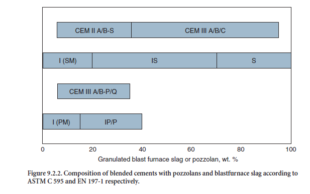
As an example, Figure 9.2.2 shows the composition of blended cements containing blastfurnace slag or pozzolans according to EN 197-1 and ASTM C 595 respectively. Detailed compositions of the blended cements are given in Table 9.2.6.
APPLICATION OF BLENDED CEMENTS FOR
CONCRETE IN EUROPE
The European standard for concrete, EN 206: Concrete – Part 1: Specification, performance, produc-tion and conformity can be described as a framework standard. EN 206 is a major step in European standardization as it defines a common terminology, common classes for exposure, and concrete characteristics for all European countries. However, EN 206 cannot operate without a complemen-tary national standard that gives additional national provisions where required or permitted by EN 206. This is primarily necessary because of the wide range of different climatic conditions in Europe, ranging from mainly dry areas in Spain and Portugal with hot summers and mild winters to countries with winter temperatures as low as minus 25°C.
EN 206 classifies the conditions concrete is exposed to during its service life into seven Exposure Classes:
• No risk of corrosion or attack (Class X0)
• Carbonation-induced corrosion (Class XC)
• Chloride-induced corrosion other than from seawater (Class XD)
• Chloride-induced corrosion from seawater (Class XS)
• Freeze/thaw attack with or without deicing chemicals (Class XF)
• Chemical attack (Class XA)
• Surface degradation by mechanical stress (Class XM)
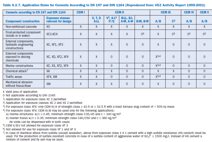
These primary exposure classes are further subdivided into 21 subclasses. Regarding the fact that not all 27 classes of cement given in EN 197 show comparable durability performance, EN 206 –together with national standards (in Germany DIN 1045-2) – gives the range of cements standard-ized under both EN 197 and DIN 1164 that are suitable for use in defined exposure classes. Portland cement (CEM I), Portland-slag cement (CEM II A/B-S), Portland-silica fume cement (CEM II/A-D), Portland-burnt shale cement (CEM II/A-T; CEM II/B-T) and Portland-limestone cement (CEM II/A-LL) may be used for durable concrete subject to all exposure conditions defined in EN 206. The use of blastfurnace cement containing more than 50% by mass of blastfurnace slag (CEM III/B) should be avoided where concrete is subject to severe attack by freezing and de-icing chemicals. For the other cement types of EN 197, there exist a variety of use restrictions, which are given in Table 9.2.7.
BLENDING MATERIALS
Granulated Blast Furnace Slag (GBFS)
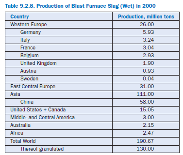
Granulated blast furnace slag is a waste product in the manufacture of pig iron. About 300 kg of slag is produced for each ton of pig iron. Table 9.2.8 shows the annual production and utilization of blast furnace slag. In 2000 in Germany, 5.93 million metric tons of blast furnace slag was produced, mostly granulated for the production of blended cements. Nearly one-third of the German cements contain granulated blast furnace slag as a main component
Chemically, blast furnace slag is a mixture of CaO, SiO2, and Al2O3,which are the same oxides that make up portland cement clinker. The proportions are already different and may vary widely depending on the composition of the raw materials and the process.
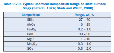
According to EN 197-1, granulated blast furnace slag for the production of blended cements should contain at least two-thirds by mass of glassy slag. Furthermore it shall consist of at least two-thirds by mass of the sum of calcium oxide (CaO), magnesium oxide (MgO) and silicon diox-ide (SiO2). The remainder consists of aluminum oxide (Al2O3) together with small amounts of other compounds. The ratio by mass (CaO + MgO)/SiO2 shall exceed 1.0. Table 9.2.9 shows typical chemical compositions of blast furnace slags.
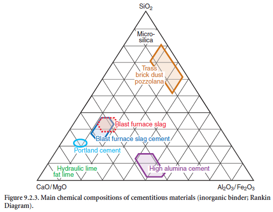
The system CaO/MgO-Al2O3/Fe2O3-SiO2 is shown Figure 9.2.3, in which the chemical composi-tion of blast furnace slags as well as of other major supplementary cementing materials are presented.
ASTM C 989 defines granulated blast furnace slag as a glassy granular material formed when molten blast furnace slag is rapidly chilled by immersion in water with or without compositional adjustments made while blast furnace slag is molten. It must solidify as glass, crystallization being largely prevented. The rapid cooling by water results also in fragmentation of the material into a granulated form. The granulated material is ground very fine (Figure 9.2.4), usually to less than 45 µm with a surface area of about 400 to 600 m2/kg. In the presence of an alkaline or sulfuric activator, it behaves like a hydraulic cementitious material.
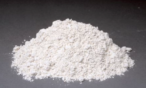
Figure 9.2.4. Ground granulated blast furnace slag (69800)
For applications in blended cement, the most important characteristics of slag are its latent hydraulic reactivity and the contribution of the slag to the development of strength and micro-structure. Essential for slag’s hydraulic activity are its chemical composition, its mineralogical composition (glass content, glass structure crystalline phases), and its granulometry (specific surface, particle size distribution, particle shape, and topology). Figure 9.2.5 shows a ground glassy granulated blast furnace slag particle in a cementitious matrix of a concrete made of CEM III/B according EN 197.
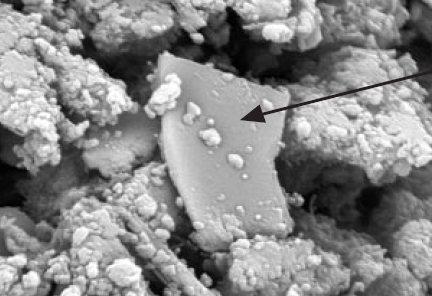
Figure 9.2.5. Blast furnace slag particle (arrow) in cement stone matrix. SEM-picture, BSE-detector (width of picture 39 µm).
Attempts have been made to establish the influence of different components in the slag on its properties. According to Satarin (1974) and Smolczyk (1980), the optimum Al2O3 content of blast furnace slag is about 13% by mass correlating with the highest strength properties of cement pastes at 28 and 91 days. A further increase of Al2O3 content leads to lower strength properties. However, there seems to be a continuous increase of 2-day strengths with increasing Al2O3 content.
The chemistry of blast furnace slag itself does not represent a definite assessment criterion for its hydraulic activity. The accelerating action of certain chemical constituents (CaO, MgO, alkalis) on the reactivity is well known, but so is the adverse action of a high proportion of SiO2.
Investigations have shown that granulated blast furnace slag with high alumina and low titanium and manganese has a high reactivity (Schneider, 2002). Blended cements produced with granulated blast furnace slag containing merwinite (Ca3MgSi2O8) have an improved strength development. Crystalline merwinite nuclei and inhomogeneity of the granulated blast furnace glass enhances the reactivity (Meng and Schneider, 2001; Schneider and Meng, 2000). Such inhomogeneties in the microstructure can be detected by using cathode luminescence radiation of scanning electron microscopy.
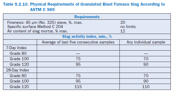
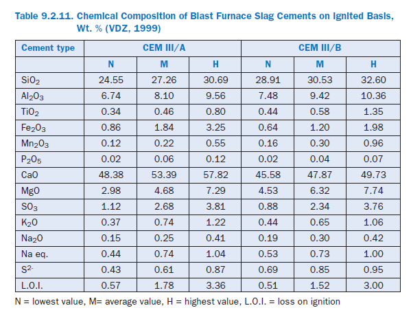
Physical requirements for granulated blast furnace slag according to ASTM C 989 are listed in Table 9.2.10. Table 9.2.11 shows the average chemical composition of different granulated blast furnace slag cements produced in Germany (VDZ, 1999).
The validity of the glass content as a direct characteristic of the blast furnace slag reactivity is restricted as well. As a rule, all German blast furnace slags have a glass content of more than 95%by mass, (VDZ, 1999). Nevertheless, slags from different works contribute quite differently to the strength and the microstructure of the cement. ASTM C 989 and C 1073 describe requirements and tests for evaluating the relative cementitious potential of a slag.
Pozzolanic Materials
Pozzolanic materials are natural substances of siliceous or silico-aluminous composition. Pozzolans consist essentially of reactive amorphous silicon dioxide (SiO2) and aluminum oxide (Al2O3). The remainder consists of iron oxide (Fe20O3) and other oxides (see Figure 9.2.3). The proportion of reactive calcium oxide for hardening is negligible. The reactive silicon dioxide content shall be more than 25.0% by mass.
When finely ground and in the presence of water, pozzolans react at normal ambient temperature with dissolved calcium hydroxide, a reaction prod-uct of the cement hydration, to form strength-developing calcium silicate hydrates and calcium aluminate compounds. These compounds are similar to those which are formed in the hardening of hydraulic materials.
EN 197 distinguishes between Natural Pozzolan (P) and Natural Calcined Pozzolan (Q). Natural pozzolans are usually materials of volcanic origin or sedimentary rocks. Natural calcined pozzolans are materials of volcanic origin, clays, shales or sedimentary rocks, activated by thermal treatment at about 800°C-1000°C. The pozzolanic activity depends on the physical form and the amounts of glass and zeolites present. If they contain more than 10% by mass of relatively unreactive clay minerals, this can appreciably lower their activity (Massazza, 1983).
Other possible sources of pozzolanic materials are ashes from burnt agricultural wastes, especially rice husk, sugar cane, or sugar bagasse. These ashes when rapidly cooled, retain a high amount of amorphous silica and alumina and can be used for preparing cementitious mortars or building units like hollow blocks (Day and others, 2000; Martirena Hernandez and others, 1998; Middendorf and others, 2003).
Although both fly ash and silica fume have pozzolanic properties, EN 197 specifies them separately. ASTM C 595 regards fly ash as a pozzolan.
Fly Ash
Fly ash is obtained by electrostatic or mechanical precipitation of dust-like particles from the flue gases of furnaces fired with pulverized coal (Figure 9.2.6). Ashes obtained by other methods shall not be used in cement according to EN 197-1.
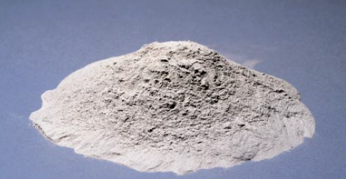
Figure 9.2.6. Fly ash is dust-like particles collected from coal-fired furnaces.
Fly ash may vary widely with respect to the morphology and the size of the particles, the content of glassy phases, and the type of crystalline material. Reactive fly ashes consist predominantly of noncrystalline silica, which is the determining factor for their pozzolanic activity. The crystalline minerals are generally quartz, mullite, hematite, magnetite, or ferrite spinel. Figure 9.2.7 shows a SEM picture of typical fly ash particles.
According to EN 197-1 fly ash may be silico-aluminous or silico-calcareous in nature. The former has pozzolanic properties; the latter may have, in addition, hydraulic properties. The loss on igni-tion of fly ash shall not exceed 5.0% by mass to prevent frost damage and/or to reduce the water demand in concrete.
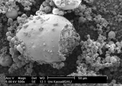
Figure 9.2.7. SEM-picture, SE-detector, fly ash particles of different sizes.
ASTM C 618 specifies fly ashes for use as concrete additions only. Class F fly ash is normally produced from burning anthracite or bituminous coal. Class C fly ash is produced from lignite or sub-bituminous coal. Class N pozzolan is defined as raw or calcined natural material, such as some diatomaceous earths; opaline cherts and shales; tuffs and volcanic ashes or pumices, calcined or uncalcined; and various materials requiring calcination to induce satisfactory properties, such as some clays and shales.
The specific surface area (Blaine) of fly ashes typically ranges between 250 m2/kg and 510 m2/kg, with 62% – 92% finer than 45 µm (Meiniger, 1981).
According to ASTM C 595, pozzolans are required to meet fineness, expansion, and pozzolanic activity index requirements (see Table 9.2.12). The latter is defined as the 28-day strength attained by replacing 35% portland cement by pozzolan cured at 38°C, and expressing this value as the percentage of the strength obtained by the same portland cement when tested under similar condi-tions and at the same moisture content.

The maximum loss on ignition requirements given in the European Standard for common cement is restricted to 5% by mass only. This is because of concerns that the unburned coal particles that form the greater part of the loss on ignition can exaggerate surface scaling of concrete under conditions of frost attack and deicer usage, the adverse effect that they can have upon air entrain-ment, and the darker color which can result if such fly-ashes are used in cement (see section on Portland-slag and Portland-fly ash).
Siliceous Fly Ash (V)
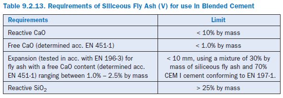
According EN 197, siliceous fly ash is a fine powder of mainly spherical particles having pozzolanic properties. It consists essentially of reactive SiO2 and Al2O3. The remaining constituents are Fe2O3 and other oxides. The main requirements are listed in Table 9.2.13.
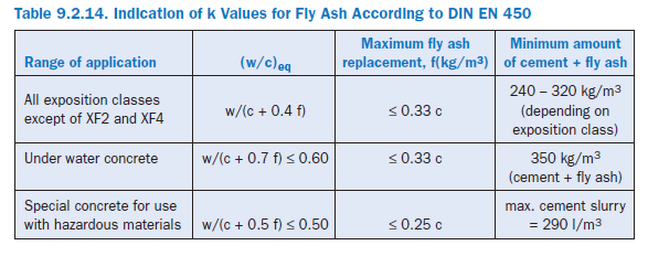
According to European Standard for Concrete EN 206-1 and the German Standard DIN 1045-2 fly ash according to EN 450 may be used as concrete addition. Depending on the exposure class, fly ash may replace from 10 to 50 kg cement per cubic meter of concrete. Its cementitious efficiency is considered by the “cementing efficiency index,” k, and by calculating the equivalent water/cement-ratio of the concrete:
(w/c) eq = w / (c + k· f)
where,
w = water
c= cement
f= fly ash
Table 9.2.14 shows the indication of k values for fly ash according DIN EN 450 and the use restric-tions given in EN 206-1.
Calcareous Fly Ash (W)
According EN 197-1 calcareous fly-ash consists essentially of reactive calcium oxide (CaO), reactive silica (SiO2) and alumina (Al2O3). Concern has been expressed that calcareous fly ash can poten-tially contain hard-burnt calcium oxide which may hydrate after some years and give rise to delayed expansion.
Calcined Shale
Calcined shale, especially the oil-shale, is produced in a special kiln mostly in power plants at temperatures of approximately 800°C, and ground to a very fine powder of average particle size of 1 to 2 µm and a surface fineness of about 700 to 750 m2/kg Blaine (Figure 9.2.8).
Owing to the composition of the natural material and the production process, calcined (burnt) shale contains clinker phases, mainly dicalcium silicate and monocalcium aluminate. It also contains, besides small amounts of free calcium oxide and calcium sulfate, larger proportions of pozzolanically reacting oxides, especially silicon dioxide. Consequently, the finely ground calcined shale shows pronounced hydraulic and pozzolanic properties. Finely ground calcined shale may have a compressive strength of at least 25.0 N/mm2 at 28 days when tested in accordance with EN 196-1.
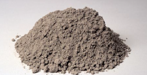
Figure 9.2.8. Calcined shale.
Limestone (L, LL)
Limestone additions to cement may have several functions: completion of the granulometric curve of cements deficient in fine grains, interaction with the hydration process, obstruction of capillary pores, water percolation, and variation of the rheological parameters of the paste.
According to EN 197-1, limestone used as a blending material shall consist of more than 75% by mass of CaCO3.In practice, e.g. in Germany, as a rule, limestones with more than 85% by mass CaCO3 are used. The clay content is tested by methylene blue adsorption. It may not exceed 1.20g/100g. The total organic carbon (TOC) content of the limestone, when tested in accordance with EN 13639, shall not exceed 0.20% by mass for CEM II A/B-LL. Limestone with up to 0.50%by mass may be used for CEM II A/B-L cements (see section on Definitions and Specifications).
The requirements in EN 197-1 have been derived from performance tests. Limestones, when ground sufficiently fine (specific surface areas > 500 m2/kg Blaine) and suitably incorporated into cements, lower the water demand and increase the strength by improving the overall particle grad-ing (see section on Granularity and Processing). Additionally, there may be a chemical effect which accelerates the hydration of the tricalcium silicate in the presence of calcium carbonate. Calcium carbonate has also been reported to react with the tricalcium aluminate to form high and low forms of the carboaluminate, CA 3CaCO33⋅⋅32H O2 and C A3CaCO⋅123⋅H2O, respectively.
Silica Fume (D)
Condensed silica fume is a byproduct of a melting process in silicon metal and the ferrosilicon industry. The reduction of quartz to silicon at temperatures up to 2000°C produces SiO vapors which oxidize and condense in the low-temperature zone to tiny spherical particles consisting of noncrystalline silica (Figure 9.2.9). Typically, individual particles have an average diameter in the order of 0.1 µm and surface areas in the range of 20,000 to 25,000 m2/kg
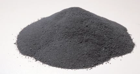
Figure 9.2.9. Silica fume powder.
According to EN 197-1 silica fume for use in Portland-Silica-Fume-Cement shall meet the following requirements: The content of amorphous silica (SiO2) < 85% by mass, the loss on ignition must not exceed 4% by mass and the specific surface area (BET) (untreated) must be higher than 150,000 cm2/g in accordance with ISO 9277. For intergrinding with clinker and calcium sulfate, the silica fume may be in its original state or be compacted or pelletized with water. Unless used with a water-reducing additive, it can be expected to increase the water demand of a cement. Also, on account of its fineness (150,000 – 200,000 cm2/g using the BET method), it has a tendency to agglomerate. As a result, special care needs to be taken to disperse it when incorporated into a cement.
Minor Additional Constituents
In addition to blending materials, fillers are also used: normally either limestone or the raw meal which constitutes the feedstock to the cement kiln system. In some cases, if the chemistry is suit-able (low alkali and chloride levels), the dust collected in the electrostatic precipitators has been used. Furthermore, calcium sulfate is added to the other constituents of cement during its manu-facture to control setting.
Additives are constituents which are typically added to improve the manufacture or the properties of the cement.
GRANULARITY AND PROCESSING
Limestone as Mineral Addition for Blended Cements
A Granulometric Approach
The properties and performance of cement-based materials are not only affected by the propor-tions and reactivity of the components but to a large extent by the particle size distributions (PSDs). Usually the PSDs of cements are represented by the parameters of Rosin-Rammler (R-R) distribution function; namely position parameter, xo, and slope, n.Varying the PSD of a cement with a given specific surface area by changing either xo at constant n,or vice-versa, affects its void volume, its water demand, and its standard strength. Increasing the slope n increases the void volume and hence the water demand.
Optimizing the PSD for a blended cement may improve its water demand, bleeding, workability, and strength development (Schmidt, 1992). However, the PSD of the mineral addition and cement must be adapted to suit each other, since reducing the void space between the cement particles is a primary purpose of the mineral additions. A large part of water formerly used to fill the void space between the cement particles now works as a lubricant and coats the particles with a film of water until the constituent particles can move freely in relation to one another. Hence, for a given water-cement ratio the workability of the cement paste can be improved to a certain extent. Alternatively, the quantity of (both) mixing water and/or plasticizer needed to produce a desired slump and workability can be reduced. However, because of standard strength development, durability, water demand, and workability, both quantity and fineness of mineral additions are limited. For exam-ple, as specified in the European cement standard EN 197, portland limestone cements are permit-ted to contain 6% to 35% limestone.
While the optimal PSDs for portland cement are well known, it is less clear how to optimize the PSD and determine the optimum mineral addition content for a blended cement. The following example illustrates the optimization of the limestone content for portland-limestone cement according to EN 197. The latter with limestone contents of 10%, 15%, and 20% by mass were produced by mixing limestone meal (specific surface area 6000 cm2/g) and two portland cements with different particle size distribution and specific surface areas of 2620 cm2/g (CEM I 32.5 R) and 3380 cm2/g (CEM I 42.5 R), respectively. Details for cements and the limestone meal are given in Table 9.2.15.
The particle size distributions of both starting materials and mixtures/blends are shown in Figure 9.2.10 to Figure 9.2.12.
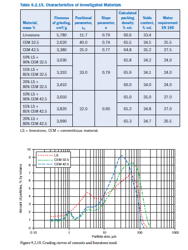
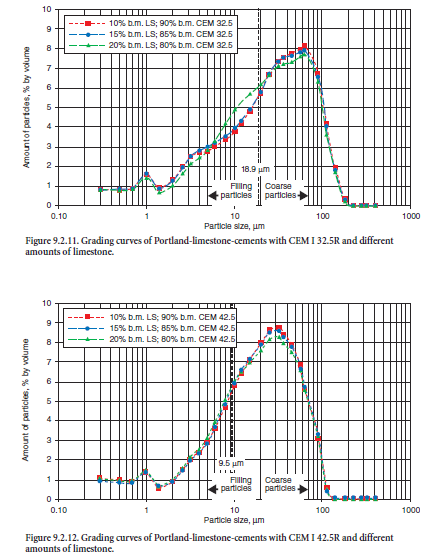
The packing density/void content of the blends were determined experimentally. The amount of water segregated within 120 minutes from 100 ml cement paste with a water-cement ratio of 0.85 is a measure for the void content. Figure 9.2.13 illustrates the effect of limestone additions on the water segregation and hence on the void volume to be filled with water. The coarser undiluted cement (CEM I 32.5) segregates about 13 ml water which corresponds to 18% of the original mixing water. An addition of 10% to 20% limestone meal reduces the void volume due to the filler effect. In this case, 20% to 28% of the original mixing water was segregated. An addition of 10% by mass limestone to the coarser cement reduced the water demand for required workability of the cement paste from 25.5% to 24% by mass.
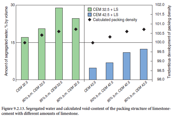
The maximum water segregation and consequently the minimum void content were observed for the blend containing 15% by mass limestone meal. An addition of 20% limestone further increased the packing density but also increased the total specific surface area and generated a higher water demand to coat the constituent particles with a film of water. In case of the finer cement (CEM I 42.5), the filler effect of limestone is less pronounced; the maximum segregation of mixing water is about 7.5%, corresponding to a limestone content of 20% by mass.
A computer simulation demonstrates that the lowering of water requirements can be attributed to the reduction of void volume by mineral additions. The model is based on the assumption that both cement and limestone particles are spheres. A filler effect exists, if the particle size distributions of the two components have been adapted to suit one another. According to Reschke (2001), an optimum filler effect is given by the following ratio:
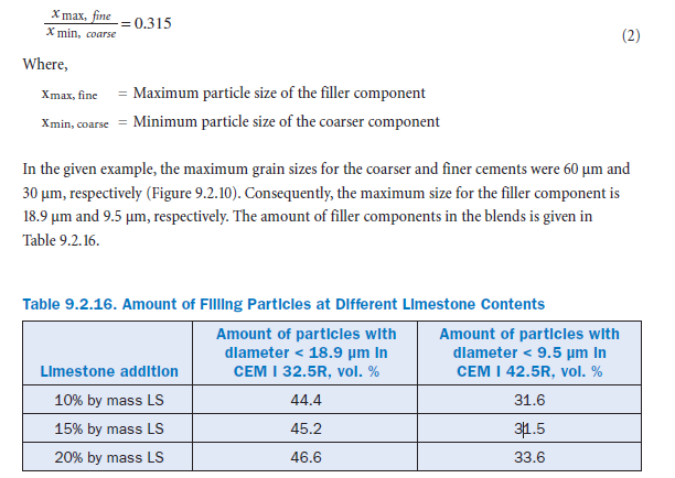
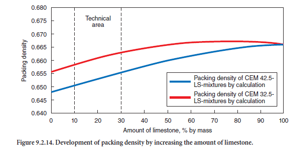
A comparison of portland-limestone cement produced from coarser cement (CEM I 32.5) and finer cement (CEM I 42.5) shows that in the latter case the filler effect of limestone is less pronounced. A simulation based on the grain size distribution allows a calculation of the packing density (Reschke, 2001; Schwanda, 1960). For this approach, the particle size distribution function is divided in several fractions and the so-called ‘range of particle handicap’ is calculated. Simply, the latter value is the product of the total volume of a certain particle class and the ratio of its grain size to a standard grain size. It is a measure for the filling effect of the fines without increas-ing the total volume of a mixture. The calculation scheme is a matrix with i particle classes as grains providing the framework (coarse particles) and i particle classes as filling particles. Furthermore, utilizing a computer-implemented calculation scheme allows a more detailed subdi-vision of particle classes (Geisenhanslueke and Schmidt, 2002).
The use of the derived parameters allows the calculation of the packing densities of both the cements and the cement-limestone mixtures used. As shown in Figure 9.2.14, the packing density increases with increasing limestone content. However, because of standard strength development and the European cement standard EN 197, portland limestone cements are permitted to contain only 6% to 35% limestone. The calculated packing density correlates with the experimentally determined amount of segregated water (Figure 9.2.13). This suggests that in cement-limestone mixtures, limestone meal indeed fills and reduces the void volume. However, parameters of the Rosin-Rammler (R-R) distribution function, namely position parameter, xo, and slope, n, alone are not suitable to optimize the fines in cements, since they are not very sensitive and do not properly reflect both the void content and particle size distribution.
PRODUCTION PROCESS
Blended cements may be produced either by grinding the constituents together in the mill or by grinding them separately and mixing them in a highly efficient powder mixer.
When clinker and limestone are interground to produce portland limestone cements, the inert limestone, which is normally easier to grind, usually builds up in the finer particle size fractions of the cement mix. The particle size distribution becomes wider, and the water demand and the strength may be positively affected. If both components are ground separately, the limestone must be ground to a fineness that provides a sufficient amount of particles which are fine enough to fill the remaining voids between the coarser grains of the clinker and/or of the cement. If the lime-stone powder used is too coarse, the water demand may rise, the segregation of water increases, and the strength of the mixed cement may be reduced more than proportionally.
The strength properties of cements containing blastfurnace slag depend primarily on the reactivity of the clinker, the hydraulic potential of the slag, the amount of slag in the cement, and its fineness. An optimization of the sulfate content affects the cement strength to a minor extent.
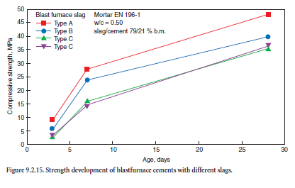
It is not possible currently to predict the latent hydraulic potential of a specific blastfurnace slag from its chemical composition only. The granulation conditions are crucial and influence the microstructure of the slag. Four industrial and 30 synthetic granulated blastfurnace slags of different chemical compositions were investigated by Wang and coworkers (2001). Figure 9.2.15 demon-strates the influence of the industrial slags on the strength development of cement mortars of GBFS cements of comparable fineness produced according to EN 196-1.
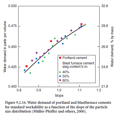
As for other cements, the water demand of blastfur-nace slag cements increases with increasing void volume of the cement. Figure 9.2.16 shows the increased water demand required of port-land cements and of blast-furnace slag-cements to achieve standard workabil-ity, measured in accordance with EN 196. It increased with increasing slope n of the R-R function. The cements studied both had the same specific surface area of 360 m2/kg.
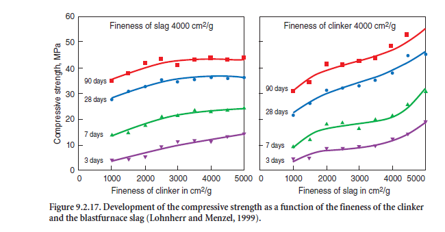
When clinker and blastfurnace slag are interground, the slag, which is harder to grind than clinker, builds up in the coarser fractions so that the hydraulic potential of the slag is only partly available. The finely ground clinker fraction tends to accumulate in the particle fractions smaller than 30 µm. This enrichment of reactive, very fine ground clinker may result in increased water demand, an earlier setting and less favorable strength properties. As an example, Figure 9.2.17 shows that with a constant slag fineness of 4,000 cm2/g there was very limited improvement in the cement strength, but obviously with a constant fineness of the clinker of 4,000 cm2/g, the strength increased with increase in specific surface area of the slag.
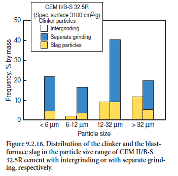
Because of these experiences, cements with slag as a main constituent (port-land-slag cements and blastfurnace-slag cements) are increasingly produced by grinding the clinker together with the sulfate, and grinding the slag separately. This allows for an optimum fineness of the constituents but requires blending in highly efficient power mixers. This gives the freedom to optimize the rheology and strength behavior with respect to the reactivity and specific grindability of both the clinker and the slag. As an example, Figure 9.2.18 shows the cumulative particle size of a portland-blastfurnace-slag cement CEM II/B-S 32.5R, with a constant fineness of 3100 cm2/g, inter-ground or separately ground and mixed. In the latter case, the share of fine slag particles was significantly higher and the contribution of the slag to the strength development of the cement was improved (Trenkwalder and Ludwig, 2001).
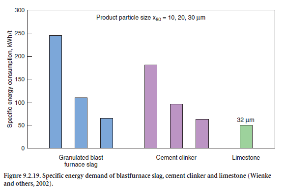
The power consumption for grinding is another important aspect of the production of blended cements. As a rule and widely independent of the material, the specific grinding energy demand increases hyperbolically with increasing fineness of the particles. Figure 9.2.19 adopted from Wienke and others (2002), shows the power requirements for grinding a granulated blastfurnace slag, cement clinker, and limestone to a particle size x80 of 10 µm, 20 µm, and 30 µm.
On the other hand, the plant throughput decreases approximately linearly with increasing fineness. These findings also support the experience that blastfurnace slag-cements are preferably produced by grinding the slag and the clinker separately to an optimum fineness but to produce portland-limestone cements, it is preferred to intergrind the clinker and the easy-to-grind limestone, to get the favorable enrichment of fine limestone particles with a minimum of grinding energy.
PERFORMANCE OF BLENDED CEMENTS
General
The strength and time-dependent strength development of cements, even of the same kind and strength class, differ widely depending on the mineralogy of the raw materials, the processing, and the reactivity of the clinker; the fineness and particle-size-distribution of the cement; the content and kind of sulfate; the ambient temperature; etc. The properties of the cement used also influence the strength and durability of concretes and other end products. That is why EN 206 in single cases restricts the application of some blended cements in concrete (see section on Application of Blended Cements for Concrete in Europe).
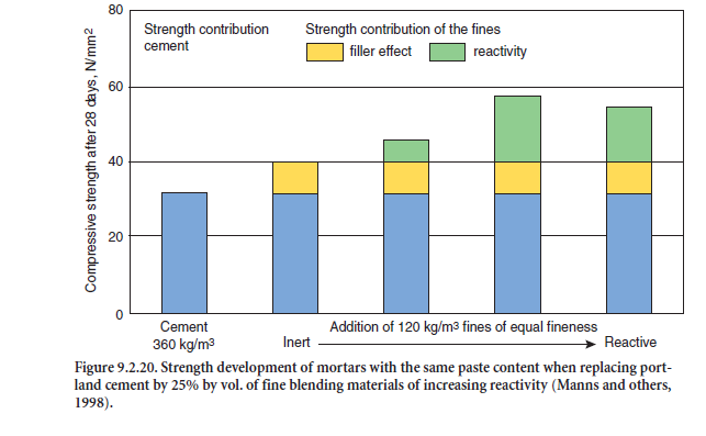
The influence of the blending material on the strength and durability behavior of mortars and concretes depends on the reactivity of the blend. Finely ground inert materials primarily affect the early strength by filling voids in the microstructure before hydration starts. With an optimum grain-size distribution, the water demand to achieve a given workability of the concrete is reduced. Reduced water demand lowers the w/c ratio, typically resulting in an increased final strength. Reactive blending materials, both by the void filling effect and the strength contribution, influence the strength capability as shown in Figure 9.2.20. The diagram shows the compressive strength of mortar with 360 kg CEM I 32.5 R to which has been added 120 kg/m3 of different fines with a fine-ness of 4000 cm2/g.
The strength and durability properties of blastfurnace slag-cements are well proven and estab-lished. Therefore the following deals primarily with properties of concretes produced with port-land-limestone, portland composite, portland-slag, and portland-fly ash cements.
Portland-Limestone-Cement
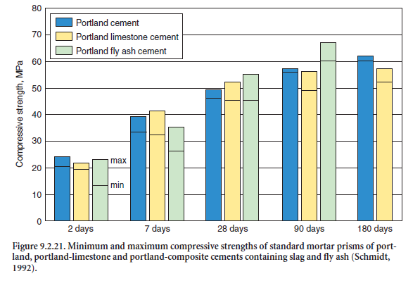
In a first survey, Schmidt (1992) compared the strength properties and main durability criteria (progress of carbonation, resistance against frost with and without deicing agents, depth of water penetration, resistance against chloride penetration, and sulfate resistance) of portland cements and portland-limestone cements CEM II/A-LL with around 15% – 20% by mass of limestone, produced in three different cement works in Germany. The raw materials and the clinkers differed widely regarding their contents of alkalies, C3A, and other relevant chemical constituents. As an example, Figure 9.2.21 shows the development and the range of the cement compressive strength tested on standard mortar prisms 40x40x160 mm in accordance with EN 196.
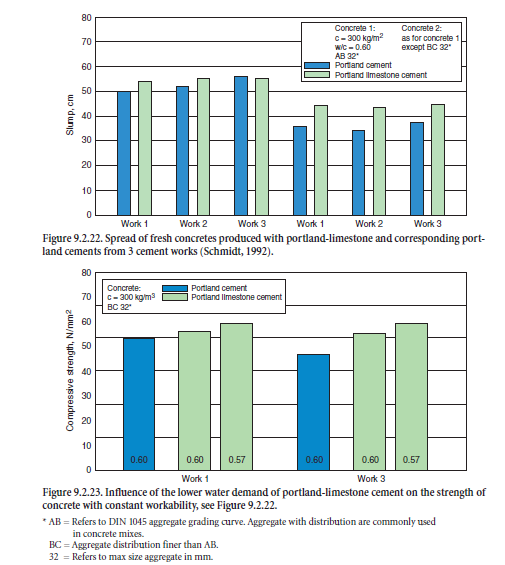
As stated before, the water demand of optimized portland-limestone cement to reach a certain workability is lower than for comparable portland cements. Figure 9.2.22 shows the significant differences in slump of fresh concrete tested in accordance with DIN 1048. In addition, Figure 9.2.23 demonstrates how the 28-days strength of concrete increases if the water content is correspondingly reduced.
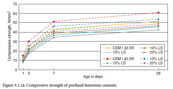
Based on laboratory and practical tests in cement works, Figure 9.2.24 further illustrates the influ-ence of fine limestone particles on the compressive strength of cement mortars due to their void filling effect. By replacing 15% by mass of the coarser portland cement CEM I 32.5R by finely ground limestone (SBlaine = 6340 cm2/g), the specific surface area of the blend rose from 2620 up to 3310 cm2/g. With constant w/c-ratio, the early strength slightly decreased by about 10%. The addition of the same amount of limestone filler to a finer ground cement (CEM I 42.5R) produced from the same clinker caused a decrease in strength up to 20% due to its wider particle size distri-bution and smaller void volume to be filled.
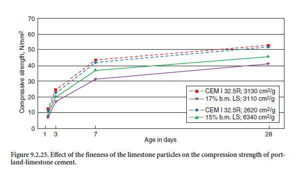
The effect of the fineness of limestone particles and their interaction with the clinker particles on standard cement strength is demonstrated in Figure 9.2.25. It shows the strength values of two different portland cements CEM I 32.5R with virtually the same strength development but with slightly different fineness (SBlaine = 262 and 311 cm2/kg) one according to Table 9.2.17 and one adopted from Reschke and others (1999). Mixed with 17% by mass of finely ground limestone filler according to Table 9.2.17 (SBlaine = 634 cm2/kg), the compressive strength was reduced by only about 10%. However mixing a cement with 17% by mass limestone filler having the same fineness as the cement (SBlaine = 311 – 3130 cm2/kg) decreases the strength by up to 30% due to the lack of pore filling particles.
In an extensive survey (Manns and coworkers, 1998), the technical properties of portland-lime-stone cements CEM II/A-L 32.5R and corresponding portland cements CEM I 32.5R produced according to EN 197 in 10 German cement plants, were compared on the basis of laboratory test results obtained during the tests for approval and certification. At the time of the study all cements had already been produced for more than 8-10 years.
The limestone content of all portland-limestone cements was close to 20% by mass. The tests described the strength development, the deformation characteristics, and the behavior with respect to corrosion protection of steel reinforcement in the concrete and of the concrete itself due to frost and to freeze-thaw attack with deicing chemicals. The tests procedures were based on EN 196 for the cement and on the German test standard for concrete, DIN 1048. The resistance to freeze-thaw with deicing chemicals substantially followed the procedure of Austrian Standard ÖNORM B 3306. The tests, the procedures used, and the concrete mixes are given in Table 9.2.17.
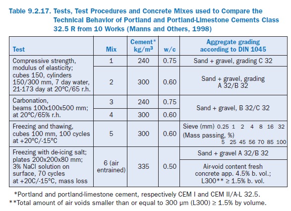
The main results are given in Figure 9.2.26 to Figure 9.2.29, adopted from Manns and others (1998). Because of the great number of results in each case, only the minimum and maximum values for both types of cement are given. The overlapping area is shaded.
As a confirmation of the results of earlier tests given in Figure 9.2.26, the variation of the initial strength and minimum strength values for the standard (mortar) strength according to EN 196 after 28 days were more or less the same for both cements. The maximum strengths after 90 and 180 days were somewhat higher for the portland cement.
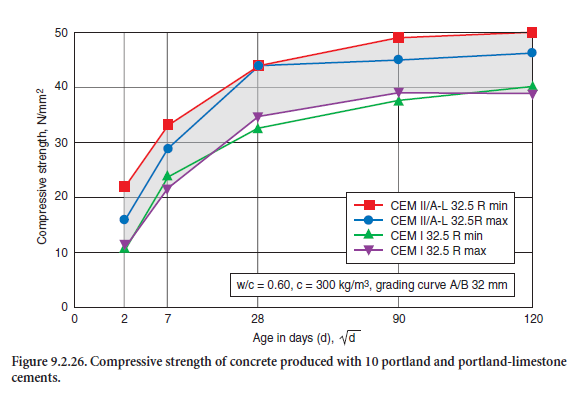
Figure 9.2.26 shows the compressive strength of concrete mixture 2 according to Table 9.2.17, a concrete of strength class C 20/25 for outdoor exposure in Mid-Europe climate (Exposition class XC according to EN 206, (see section on Application of Blended Cements for Concrete in Europe). The characteristic strength values and the strength development are in a narrow range for both cements. The differences appear to be insignificant from the practical construction point of view. The static modulus of elasticity at 90 days of that mixture was about 30,000 MPa (27,000 – 32,000 MPa.
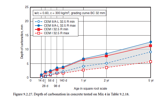
The carbonation progress of concrete mix 4, stored under dry laboratory conditions from 14 days to up to 5 years, is shown in Figure 9.2.27. Up to one year, the ranges of scatter were virtually identical; thereafter the minimum carbonation values were slightly higher for the portland-limestone cements. The values for mixture 3 were significantly higher for both cements, due to the higher w/c ratio and its higher porosity (minimum value 12 mm, maximum value 20 mm after 5 years). As a rule, the car-bonation progress in a structure under real moisture conditions is much slower. In combination with a proper concrete cover, in both cases the steel reinforcement is equally protected against corrosion.
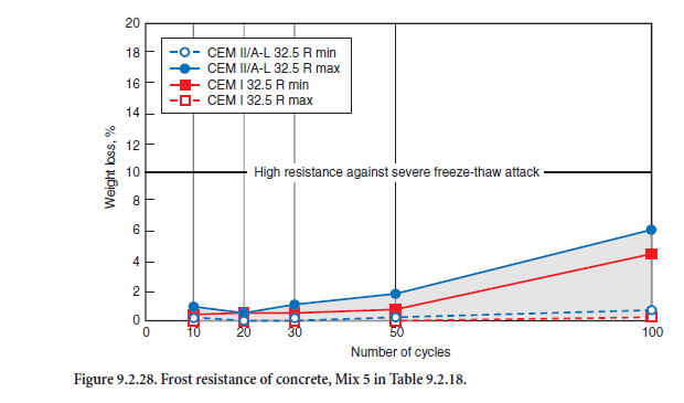
The results of the freeze-thaw tests are shown in Figure 9.2.29. According to the limits given for this test procedure, the loss of mass after 50 freeze-thaw cycles should not exceed 5% by mass and after 100 cycles 10% by mass. All test results were significantly lower. That means that both the concretes made with portland cement and with portland-limestone cement showed a sufficiently high resist-ance against frost attack.
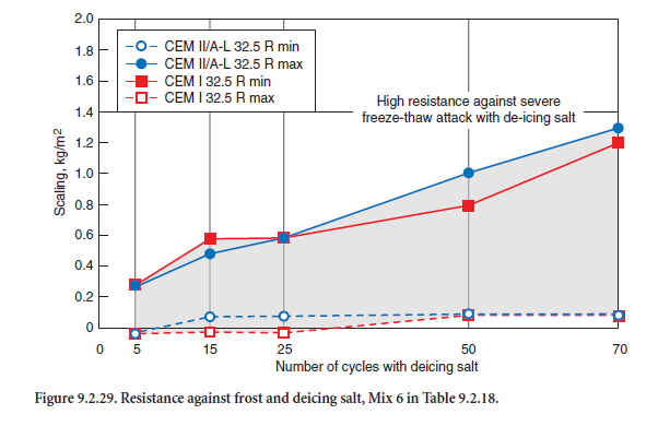
The very same can be stated regarding the resistance of the air entrained concrete Mix 6 according to Table 9.2.17. As Figure 9.2.29 shows, the range of results was identical for both cements. After 70 cycles all losses of mass were far below the upper limit of 1.4 kg/m2 for this test procedure.
According to the European Standard for Concrete EN 206, portland-limestone cements CEM II/A-LL according to EN 197 with up to 20% high quality limestone may be used like portland cement for all concrete applications. In practice the limestone content is between 15% – 18% by mass. From the practical point of view, the strength and deformation behavior as well as the resistance against carbonation, chloride diffusion, frost, and de-icing salts of properly produced portland-limestone cements are fully comparable to and in some attributes better than that of portland cements of the same strength class.
The European Cement Standard also allows the production of portland-limestone cements with higher limestone contents up to 35% by mass and/or the use of less pure limestone (CEM II/A-L, CEM II/B-LL or CEM II/B-L according to EN 197). The use of portland-limestone cements with more than 20% by mass high grade limestone is not permitted for concrete with high resistance against deicing salt or for constructions having contact with sea water. Because of their partially lower capability, portland-limestone cements with more than 20% by mass limestone should only be used for non-reinforced concrete or for applications without risk of frost attack (see Table 9.2.7).
The properties of portland-limestone cements and their behavior in fresh and hardened concrete or in other end products directly correspond with their particle size distribution. The fineness of both components should be adapted to suit one another in a way that the limestone contains a sufficient amount of fine particles filling the voids in between the cement grains.
Portland-Slag Cements and Portland-Fly Ash Cements
Portland-blastfurnace slag cements with up to 20% – in some countries up to 35% by mass – of ground blastfurnace slag (CEM II/A or B-S according to EN 197) are well established in most European countries. Portland-slag cement may be used for all kinds of concrete and all exposure classes of EN 206.
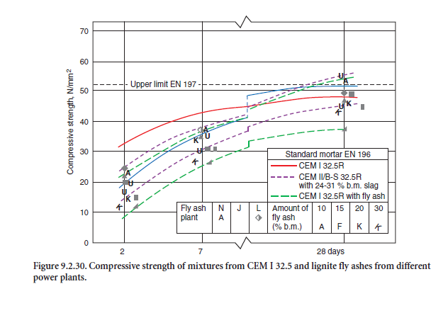
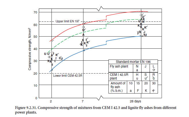
Some test results regarding their strength properties are given in Figure 9.2.30. and Figure 9.2.31.
As a rule, the early strength at an age of 1, 2, and 7 days is somewhat lower than for portland cements made from the same clinker. In areas with low ambient temperatures in the winter time it might be favorable to reduce the amount of slag within the limits of a given product class – e.g. from 35% to 21% by mass for a CEM II/B-S cement – to increase the early age strength. It might even be necessary to change the production from CEM II/B to CEM II/A-S.
Portland-fly ash cements with up to 20% by mass siliceous fly ash (CEM II/A-V according to EN 197 (see Table 9.2.6) as well as cements with siliceous fly ash and slag – so called portland-composite cement according to EN 197 – are produced in both strength class 32.5 R as well as 42.5 R. The early strength depends considerably on the reactivity of the fly ash – especially on the amount of amor-phous glass, and the fineness of both components and the grain size distribution of the cement. Some test results regarding their strength properties are given in Figure 9.2.30 and 9.2.31.
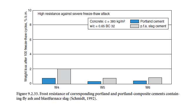
Portland-fly ash cements and portland-composite cements have proven their sufficient strength and durability in concretes for indoor and most of the outdoor applications listed in EN 206. As an exam-ple, Figure 9.2.32 and Figure 9.2.33 show the carbonation and frost resistance of concretes made with three different portland-composite cements CEM II/B-M 32.5R, each containing 15% by mass of blastfurnace slag and 15% by mass of fly ash tested in the laboratory (Schmidt, 1992). From the prac-tical point of view, both were comparable to the corresponding portland-cements CEM I from the same cement works.
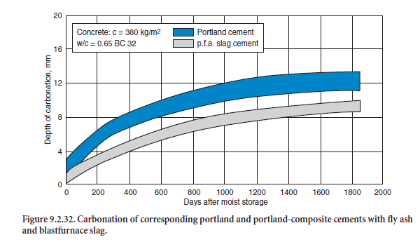
One of the main fields of application for these cements are mortars and grouts. Compared to both ordinary portland cements and portland-limestone cements, they often improve the workability and significantly reduce the segregation of water from fresh mortars, especially when the mortars are pro-duced from coarser sands.
There is limited experience with calcareous fly ashes for use in cement up to now. In comprehensive studies (Dietz, 1996; Schmidt, 1999; Schmidt and coworkers, 1997) the strength potential and some durability aspects of different portland-fly ash cements with 10% to 30% by mass calcareous fly ash from three lignite power plants in Germany were analyzed. The cements were mixed in the laboratory and compared with the corresponding portland cements CEM I 32.5 R and CEM I 42.5 R and with portland-slag cements containing 24% to 31% by mass blastfurnace slag from five cement works. The compressive strength values for the PFA cements mixed from CEM I 32.5 R according to EN 197 are already given in Figure 9.2.30, and for CEM I 42.5 in Figure 9.2.31.
When mixed with CEM I 32.5 R, the technically important early strength at 2 and 7 days was reduced by 10% to 60% depending on the amount of fly ash. But with 10% fly ash, the strength of 20 N/mm2 after 2 and of 37 N/mm2 after 28 days still exceeded the lowest values of the portland cements included in the study. The compressive strength values for all mixes containing 20% by mass of calcareous fly ash or more were significantly lower than those for the CEM II/B-S with up to 31% of slag.
The 2-day compressive strength of the cement mixtures made from CEM I 42.5 with 30% by mass of calcareous fly ash exceeded the minimum strength limit for CEM I 42.5 R of 20 N/mm2 given in EN 197. With regard to their 28-day compressive strength, most of the mixtures would have to be classified as class 42.5 or class 52.5 cements.
The laboratory tests confirmed the provisions for portland-fly ash cements produced with calcareous fly ashes given in EN 197. It seems possible to produce blended cements with adequate calcareous fly ash content which fulfill both the strength requirements of EN 197 and provide sufficient resistance of concrete when exposed to moderate ambient conditions.
REFERENCES
Standards
ASTM Standard C 150-02, Standard Specification for Portland Cement, American Society for Standards and Materials, West Conshohocken, Pennsylvania, 2002.
ASTM Standard C 219-12, Standards Terminology Relating to Hydraulic Cement, ASTM, West Conshohocken, Pennsylvania, 2002.
ASTM Standard C 595-02, Standard Specification for Hydraulic Cement, ASTM, West Conshohocken, Pennsylvania, 2002.
ASTM Standard C 618-01, Standard Specification for Coal Fly Ash and Raw or Calcined Natural Pozzolan for Use as a Mineral Admixture in Concrete, ASTM, West Conshohocken, Pennsylvania, 2001.
ASTM Standard C 989-99, Standard Specification for Ground Granulated Blast-Furnace Slag for Use in Concrete and Mortars, ASTM, West Conshohocken, Pennsylvania, 1999.
ASTM Standard C 1157-00, Standard Performance Specification for Hydraulic Cement, West Conshohocken, Pennsylvania, 2000.
ASTM Standard C1073a-97, Standard Test Method for Hydraulic Activity of Ground Slag by Reaction with Alkali, ASTM, West Conshohocken, Pennsylvania, 1997.
DIN EN 196-1, Publication date:1995-05 Methods of testing cement – Part 1: Determination of Strength; German version EN 196-1:1994.
DIN EN 196-2, Publication date:1995-05, Methods of Testing Cement – Part 2: Chemical Analysis of Cement, German version EN 196-2:1994.
DIN EN 197-1, Publication date:2001-02, Cement – Part 1: Composition, Specifications and Conformity Criteria of Common Cements, German version EN 197-1:2000.
DIN EN 206-1, Publication date:2001-07, Concrete – Part 1: Specification, Performance, Production and Conformity, German version EN 206-1:2000.
DIN EN 450, Publication date:1995-01, Fly Ash for Concrete – Definitions, Requirements and Quality Control, German version EN 450:1994.
DIN EN 13639, Publication date:2002-07, Determination of Total Organic Carbon in Limestone, German version EN 13639:2002.
ISO 9277, Publication date:1995-05, Determination of the Specific Surface Area of Solids by Gas Adsorption Using the BET Method.
Publications
CEMBUREAU, Personal communication. Association Européenne du Ciment The European Cement Association, 2002.
Day, R. L.; Martirena Hernandez, J.F.; and Middendorf, B., “Use of Agriculture Wastes for the Production of Energy and Building Materials,” Proceedings of the 8th International Energy Forum, Las Vegas, pages 981-986, 2000.
Dietz, S., Mineralogische, Chemische und Baustofftechnische Eigenschaften von Braunkohlenfilteraschen-Zement-Systemen, PhD Thesis, University Heidelberg, 1996.
Geisenhanslueke, C. and Schmidt, M., Computergestützte Modellierung und Berechnung zur Ermittlung der Packungsdichte von Schüttgütern, Kassel, unpublished, 2002.
Lohnherr, L. and Menzel, K., “Operating Experience With the Production of Slag Cements in a Roller Mill,” Zement-Kalk-Gips, 52(3), pages 136-146, 1999.
Manns, W.; Thielen, G.; and Laskowski, C., “Bewertung der Ergebnisse von Prüfungen zur bauauf-sichtlichen Zulassung von Portlandkalksteinzementen,” Beton, 48(12), pages 779-784, 1998.
Martirena Hernandez, J. F.; Middendorf, B.; Budelmann, H.; and Gehrke, M., “Use of Wastes of the Sugar Industry as Pozzolana in Lime-Pozzolana Binders,” Cement and Concrete Research, 28(11), pages 1525-1536, 1998.
Massazza, F., “Clinker Pozzolana Cements,” 7th International Ready Mixed Concrete Congress. Progress in Cements to Improve Competitiveness of Concrete, London, 1983.
Meiniger, R. C., Use of Fly Ash in Air-Entrained Concrete, Report of Recent NSG-NRMCA Research Laboratory Studies, National Sand and Gravel Association: 32 pages, 1981.
Meng, B., and Schneider, C., “Microscopical Investigation of Crystalline Structures in Blast Furnace Slag Glasses Using Cathodoluminescence,” Proccedings of the 8th Euroseminar on Microscopy Applied to Building Materials, Athen, pages 34-37, 2001.
Middendorf, B.; Mickley, J.; Martirena Hernandez, J. F.; and Day, R. L., “Masonry Wall Materials Prepared by Using Agriculture Waste, Lime and Burnt Clay,” Masonry: Opportunities for the 21st Century, ASTM STP 1432, D. Throop and R.E. Klingner (Editors), American Society for Testing and Materials, West Conshohocken, Pennsylvania, (in press), 2003.
Müller-Pfeiffer, M.; Ellerbrock,H.-G.; and Sprung, S., “Factors Effecting the Properties of Cements with Several Main Constituents,” Zement-Kalk-Gips, 53(5), pages 241-247, 2000.
Reschke, T., Der Einfluss der Granulometrie der Feinstoffe auf die Gefügeentwicklung und die Festigkeit von Beton, Verein Deutscher Zementwerke e.V., 2001.
Reschke, T.; Siebel, E.; and Thielen, G., “Influence of the Granulometry and Reactivity of Cement and Additions on the Development of the Strength and Microstructure of Mortar and Concrete,” Beton, 49, 50(12, 1), pages 719-724, 47-50, 1999.
Satarin, V. I., “Slag Portland Cement,” 6th International Congress on the Chemistry of Cement, Moscow, 1974.
Schmidt, M., “Cement with Interground Additives – Capability and Environmental Relief,” Zement-Kalk-Gips, 45(2, 6), pages 64-69, 296-301, 1992.
Schmidt, M., Verwertung von Braunkohlenflugaschen in Zement – Wirtschaftlichkeit und Marktchancen, Heidelberg, 1999.
Schmidt, M.; Dietz, S.; and Miskiewicz, K., “Properties of Cement Containing German Lignite Fly Ashes,” 10th International Congress on the Chemistry of Cement, Göteborg, 1997.
Schneider, C., Charakterisierung von Zementbestandteilen, Proceedings of the 41 Forschungskolloquium des DAfStb, Düsseldorf, pages 15-26, 2002.
Schneider, C., and Meng, B., “Bedeutung der Glasstruktur von Hüttensanden für ihre Reaktivität,” 14, ibausil, Weimar, pages 455-463, 2000.
Schwanda, F., “Das rechnerische Verfahren zur Bestimmung des Hohlraumes und Zementleimanspruches von Zuschlägen und seine Bedeutung für den Spannbetonbau,” Zement und Beton, pages 8-17, 1960.
Smolczyk, H., “Structure of Slags and Hydration of Slag Cements,” 7th International Congress on the Chemistry of Cement, Paris, pages 3-17, 1980.
Stark, J., and Wicht, B., Zement und Kalk – Der Baustoff als Werkstoff, Birkhäuser Verlag, Basel, 2000.
Trenkwalder, J., and Ludwig, H.-M., “Producing Slag Cements by Separate Grinding and Subsequent Mixing at the Karlstadt Work,” Zement-Kalk-Gips, 54(9), pages 480-491, 2001.
van Oss, H. G., USGS Mineral Industry Survey, U.S. Geological Survey Minerals Yearbook, 2000.
VDZ, Activity Report 1996-1999, Verlag Bau+Technik, Düsseldorf, 1999.
Wang, P. Z.; Trettin, R.; Rudert, V.; and Umlauf, R., “Influence of Primary Phase Separations on the Hydraulic Reactivity of Blastfurnace Slag Quenched by Granulation,” Zement-Kalk-Gips, 54(11), pages 646-653, 2001.
Wienke, L.; Lander, S.; and Stark, U., “Investigations into Grinding of Raw Materials, Waste and Intermediate Products in a Pilot Plant,” Zement-Kalk-Gips, 55(8), pages 39-48, 2002.