Contents
To download the below and all other Useful Books and calculations Excel sheets please click here
To download the below and all other Useful Books and calculations Excel sheets please click here
Coarse size reduction of raw materials in Cement Industry
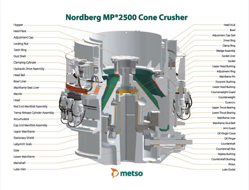
Cement raw material blasted in the quarry, requires size reduction for further processing. Size reduction is performed in crushers and grinding mills. Crushing is comminution in the coarse range, whereas grinding refers to comminution in the fine range. The technique of size reduction was developed chiefly by empirical analysis.
A variety of processes and equipment are available for selection of the right kind of size reduction machi nery; however, experience gained in this field and thorough knowledge of all possibilities of application are still deciding factors.
Size reduction machinery and methods
A Machinery for size reduction in the coarse range (crushers) by application of compression:
- Jaw crushers
- Gyratory crushers, cone crushers
- Crushing rolls
B Crushers for size reduction by impact:
- Hammer crushers or hammer mills (single or double impeller type)
- Impact crushers
C For comminution in the fines range (grinding mills) by application of impact:
- Ball mills
- Tube mills
- Compound mills
These mills are generally called gravity mills or also slow running mills.
D Mills where compression is applied for the pur pose of comminution:
- Ring ball mills (Peters-mill)
- Ring roll mills, also called bowl mills; grinding pressure is maintained either by heavy steel springs (spring type mills) or hydraulically, thus pressing the rolls or balls against the grinding bowl or ring (Loesche-mill).
As to the path of the material the following distinctions are made.
E The crushing procedure
- Crushing in single passi the crushed material passes the crusher only
- Crushing in closed circuiti for the purpose of reduction to the required size, the scalped oversize material is returned to the crusher, thus passing through the crusher two or more times.Crushing may also be combined with predrying.
F The grinding procedure:
- One pass grindingi the ground material passes through the mill only This kind of grind ing is also called open circuit grinding.
- Closed circuit grinding
Coarse particles separated from the fines mechanically or pneumatically, are returned to the mill for comminution to the required size, thus passing through the mill two or more times. Closed circuit grinding is also employed for wet grinding.
G In reference to the mill feed:
- Dry grindingi the material is fed into the mill in a dry
- Drying-grindingi the mill feed is moist and is being dried during grinding by heat supplied from
- Wet grinding an appropriate amount of water is added to the mill feed in order to be grindable in the slurry
Reduction ratio
The degree of reduction (n) is the ratio of the largest linear dimension of the material before crushing (D) to the largest linear dimension after crushing (d)i it is expressed as

If e. g. the linear dimension of the crusher feed equals 40 inches and that of the crushed material is 2 inches, then the reduction ratio

at a particle size of 0.8 inches of the crushed material, the reduction ratio

The reduction ratio of primary crushers employed in the cement industry is within the limits of n = 5 to The comminution is sometimes performed in two and also in three stages, depending upon the requirements of the raw material.
In a two-stage comminution arrangement limestone rocks are first reduced in a primary crusher from sizes between 27 and 35 inches to sizes between 5 and 8 inches, n 5. A secondary crusher reduces the material to sizes between 3/4 and 1 inch. The resulting material is then fed into the tube mills. To increase the throughput of the tube mills, a tertiary crushing stage in which the material is reduced down to about 0.12 and 0.20 inches, is sometimes provided.
In addition to previously cited definitions and with reference to maximum particle sizes, the following definitions for the degree of reduction are still employed:
- Degree of reduction which refers to the 95% particle sizes

D95 = 95 % particle size D in the feed
d95 = 95% particle size din the reduced material
In the United States, according to Bond’s size reduction theory, the 80 % particle size ratio is in use.
2- Degree of reduction which refers to the mean particle sizes

Dma = mean arithmetic particle size in the feed dma = mean arithmetic particle size in the reduced material
3 -Effective degree of reduction of a size reduction machine

s = width of discharge opening of the size reduction machine
4 – Apparent degree of reduction of a size reduction machine

m : feed opening of the size reduction machine
s : width of the discharge opening
It should be mentioned that recently, two definitions are in use, i.e. “reduction ratio'” and “degree of reduction'”. According to this, the degree of reduction expresses the difference between the initial and the final surface of the crushed material, whereas the reduction ratio denotes the relation between the initial and the final particle size.
Generation of surface and power requirement
The specific power requirement for crushing, i. e. the consumption of energy per ton of crusher feed is substantially lower for size reduction in the coarse range than for fine size reduction, i. e. for grinding. However a comparison of the energy consumption for the surface produced, shows just the contrary. To substantiate this, Mittag makes a comparison, which is quoted below in a somewhat version.
Example
Coarse size reduction:6000 kg of quartzite was crushed in a cone crusher for one hour; a feed particle size of 5-50 mm was reduced to a pr,oduct particle size of 0- 5 mm. The crusher’s power input was 18 kWh, i.e. a specific energy consumption of

ton. Then a representative sample was used to determine the surface produced by crushing. To simplify the calculation, a feed quantity of 1000 kg was taken into account. It was assumed thi:lt this quantity consisted of quartzite cubes with an edge length of 1 em, and a specific gravity of 2.5 grams/ cm3. Thus 1000 kg of crusher feed contains

400,000 cubes with a surface of 6 cm2 each; the total surface of the feed is then 400,000 x 6 = 2.400,000 cm2. After crushing it was found that 1000 kg of product shows a surface of 80,000,000 cm2. Deducting the original surface, the surface produced is then 80,000,000- 2.400,000 77,600,000 cm2, for which 3 kWh were consumed. Referring to 1 kg of crushed product, the corresponding figures are: 77,600 cm2 (77.6 cm2/gram)

meterkilogram; thus 367,000 x 0.003 = 1.101 mkg or 110,100,000 gram · centimeter. When referring to the surface produced, the power requirement

2 – Fine size reduction (grinding). Clinker and gypsum were ground in a tube mill with a specific power requirement of 30 kWh per 1000 kg cement, with a Blaine number of 3000 cm2/gram. The specific
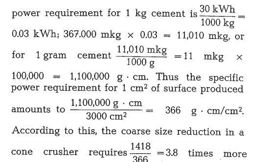
energy than fine grinding in a tube mill. This ratio might be higher when employing a jaw crusher.
Selection of crusher sizes
The selection of the proper feed openings of gyratory and jaw crushers depends on sizes of the rocks as well as upon the bucket volume of the quarry excava tor. The rock size is a function of the passing opening of the dipper or vice versa. These factors have to be adjusted to crusher capacity.
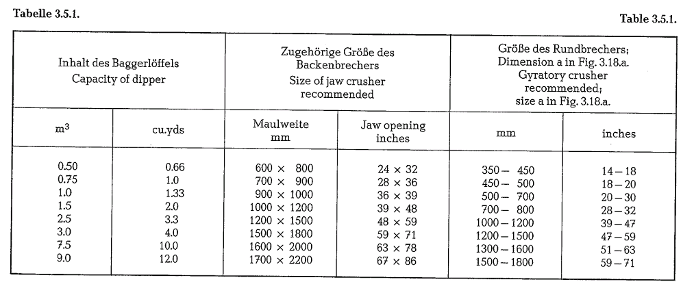
Table 3.5.1. contains feed openings of jaw and gyra tory crushers depending upon the capacity of excavator dippers.
Jaw crusher
In the cement industry the jaw crusher is in general use; this is due to its relatively simple design and also to the circumstance that this crusher is manufactured in large units. The jaw crusher serves mainly as i primary crusher (see picture shown in Fig. 3.1.) [30].
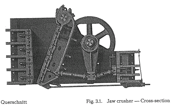
The size reduction of the crusher feed is performed between two crusher jaws; one of them is stationary, and the other is moved by toggle pressure. The jaws are lined with ribbed liners consisting of chill cast or quenched steel. The crusher frame consists of cast steel; frames of large units consist of 4 to 6 assembled sectional steel frame plates.
Fig. 3.2. shows the crushing action of the ribbed liners of the jaw crusher.

The surface of the liners is ribbed lengthwise. Fig. 3.3. shows various designs of ribs of jaw crusher liners.
To crush hard, semi-hard and brittle rocks, ribbed liners as shown in Fig. 3.3.a. are used. The included angle of the ribs amounts to 90- 100°. For crushing of coarser and considerably harder rocks,

the ribs should be corrugated as shown in Fig. 3.3.b.; here the rib angle should be 100- 110°. For large and very hard rocks, liners with more widely spaced ribs are used (see Fig. 3.3.c.). The most effective ratio between the rib width and its height as shown in Fig. 3.3.a. is expressed as

Depending on the size of the crusher feed, the width of the ribs in jaw crushers employed as primary crushers is 50-150 mm. Jaw crushers employed as secondary crushers have ribs with a width of 10-40 mm.
The width of the crusher’s discharge opening e (Fig. 3.3.a) is being measured from the top of the rib of one liner to the opposite notching of the other liner (see Fig. 3.3.a and 3.3.b); at Fig. 3.3.c it is the distance between the planes.
When working very hard materials the ribs generate lateral forces which have a negative influence on the swing jaw shaft; in such cases even jaw liners are preferred.
For the precrushing of limestone, so-called superelevated ribs are succesfully employed. Every third or fourth rib has a greater height than the normal liner ribbing. Formation of lamellar or needleshaped pieces in the crushed materials is hereby prevented. Fig. 3.4. shows such a profile of a crusher jaw liner.
The greatest wear shows at the lower part of the fixed jaw plate; next the lower part of the swing jaw plate. The constructional design of the jaw liners makes it possible to turn over a worn jaw liner 180°,


The angle enclosed by the crusher jaws is relatively small and amounts to 15-20°. This angle determines the ratio of reduction of the jaw crusher. The smaller this angle, the lower the reduction ratio. A jaw angle of 15-20° results in a reduction ratio of 4 to 6.
Various jaw crushers with different design features have been developed; of them generally two types remained master of the field, namely the double-tog gle jaw crusher (also called Blake-crusher), which is shown in Fig. 3.9. and the single-toggle jaw crusher shown in Fig. 3.10. [35].
In the double-toggle jaw crusher the movement of the swing jaw is oscillating; thus the crusher feed is being squashed. High compression is applied not only to the crushed material but also to the crusher jaws. This crusher serves for size reduction of hard and very hard material in the form of large size rocks.
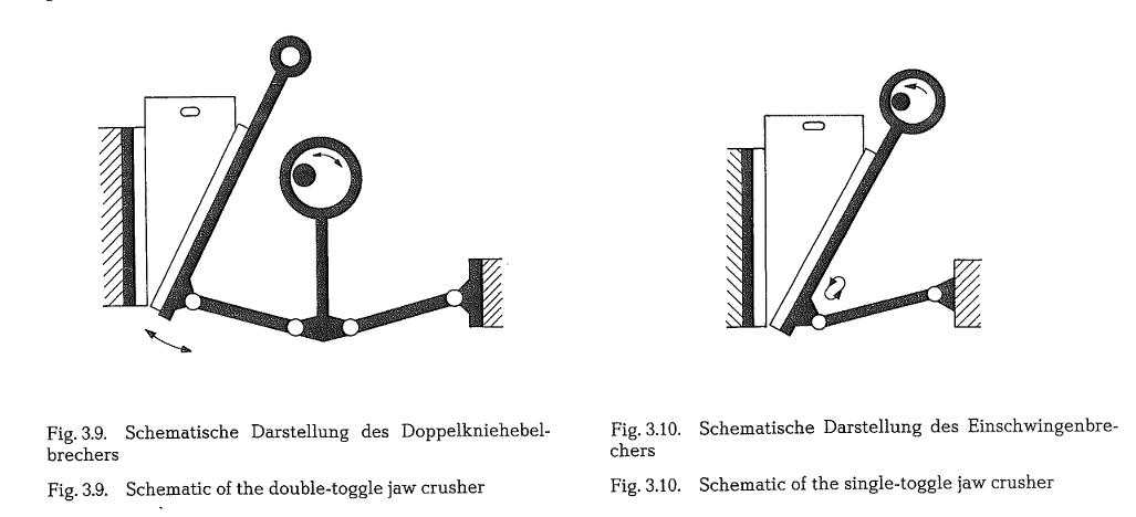
In the single-toggle crusher (Fig. 3.10.) the motion of the swing jaw is different from that of the double – toggle crusher. Here the swing jaw moves not only backwards and forwards but also up and down. The size reduction is characterized by attrition and squashing. Compression and friction work simulta neously. This crusher is employed for the reduction of semi – hard material in smaller feed sizes.
Speed of rotation
In addition to its size, the throughput capacity of a jaw crusher is also determined by the number of revolutions. However, the speed of rotation should not be excessive, since practical experience has proved that an increase in speed beyond a certain limit does not yield an increase in capacity. The back wards and forwards motion of the swing jaw must be regulated so as to give the crushed material enough time to leave the discharge opening of the crusher. The formula derived for the speed of rotation of the jaw drive is

Notation:
n Number of revolutions/min
a Angle of the crusher jaws, degree
s Way length of swing jaw, centimeter
Example: The feed opening of a jaw crusher is 900 x 1200 mm, jaw crusher angle is 22°, way length of swing jaw is 3 centimeter; then

However, regarding the friction between the crusher feed and the crusher jaws, the manufacturer recom mends an upper limit of 170 rpm [36].
The same formula conforming to more practical values has been modified and reads

Assuming that a = 20°, which generally applies to jaw crushers, the formula for the speed of rotation is

Overload safety device
If unbreakable objects such as tramp iron, digger teeth, etc., enter the crusher, they can cause consider able damage to the crushing elements. To prevent this, toggle plates which shatter, when tramp iron causes an overload were developed as safety devices for protecting the crusher from serious damage. Two different modifications of safety toggle plates with predetermined cracking lines are shown in Fig. 3.11.

After cracking, the toggle plates have to be replaced; this usually results in an extended interruption of production time. To avoid this, a hydraulic overload safety device has been developed; because of it, uncrushable objects can automatically be removed from the crushing space without any interruption of operation. Fig.. 3.12. shows the functional operating scheme of the hydraulic safety overload device [37].

With this construction the stationary crushing jaw is designed as a swing jaw, capable of giving way and having its fulcrum at the upper end. The lower end is supported on three hydraulic cylinders the pistons of which are in the front .end position when the swing jaw is closed. In case an uncrushable object enters the space between the crushing jaws, the resulting over pressure in the hydraulic system opens the jaw and the foreign matter falls out of the crushing space. Subsequently, the hydraulic cylinders move the swing jaw back to the normal operating position. During this procedure the feeding of the material to be crushed is automatically interrupted, whereas the crusher drive runs continuously. The increase in investment cost for the hydraulic protection device is approximately 25 % of the crusher price.
Capacity
A practical formula for the determination of the capa city of jaw crushers was developed by Taggart; it reads:

Notation:
Q Crusher capacity, t/h
b Width of jaw, centimeter
d Size of crushed material, centimeter
This formula generally complies with practical results achieved with medium size crushers. For large size crushers this formula yields lower capacity figures.
Lewenson developed the following formula for the capacity determination of jaw crushers
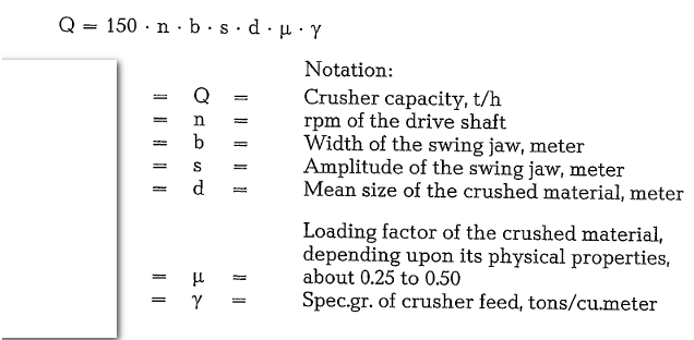
Example 3.1.
Calculate the capacity of a jaw crusher; the available data are: rpm of the main drive shaft is 170, width of swing jaw is 1.2 meter; amplitude of swing jaw is 45 mm = 0.045 meter. Mean size of the crushed material is 0.17 meter; spec. gravity of crusher feed is 2.7 tons/cu.meter.

Thus, although through different methods, both for mulas give as a result the same capacity figure for the jaw crusher
Prescott developed a rule of thumb according to which the capacity of a jaw crusher amounts to about 0.1 t/h per square inch of the jaw crusher’s feed opening.
Giesking developed a capacity formula which is applicable to both jaw and gyratory crushers; the formula reads:
![]()


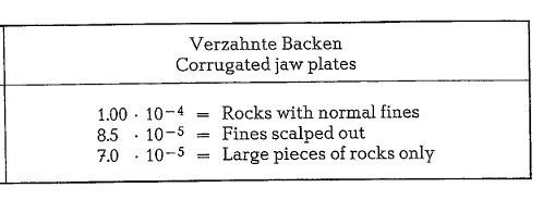
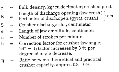
Example: 3.2.
Calculate the capacity of a jaw crusher having a feed opening of 1200 x 900 millimeter, a stroke number of 180 per minute; the length of the jaw amplitude e = 4 centimeter, and the width of the discharge slot S = 20 centimeter. The jaw plates are smooth; the crusher jaw angle is 19° (b = 1.21). Crusher feed is limestone, not prescreened (large rocks only), with a bulk density y = 1.7. It is assumed that n = 0.8.

The same formula can be calculated in U.S. engineer ing units; then the c-factor has the following values [38].

Example 3.3.
Calculate the capacity of a jaw crusher, given the fol lowing data: feed opening of crusher 47 x 36 inches, number of strokes 180 per minute, length of jaw amplitude e = 1.5 inches, width of discharge slot is 8 inches; bulk density of crusher product is 100 lb per cubic foot; all other conditions are the same as in the foregoing example.

Drive power
The drive power of jaw crushers is calculated as fol lows:
According to Viard’s formula
![]()

According to Lewenson ‘sformula
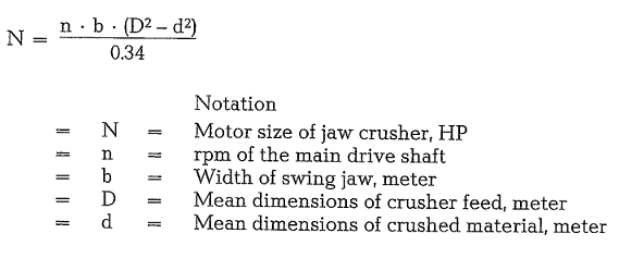
Example 3.4.
Calculate the motor size of a jaw crusher; the required data are: Width of crusher jaw 1.2 meter, revolutions of the main shaft are 170 rpm. Dimensions of crusher feed are 0.50 to max. 0.65 m; dimensions of crushed material 0.17 m
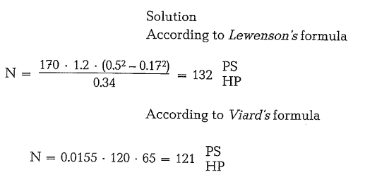
For safety reasons a 10-15% stronger motor has to be selected to overcome contingent irregularities in the supply of crusher feed. The practical index for power consumption for crushing medium hard lime stone amounts from 0.3-0.6 kWh/cu.meter of crusher feed [39].
Practical figures for energy consumption for size reduction of 1 cubic meter in jaw crushers of different sizes are:

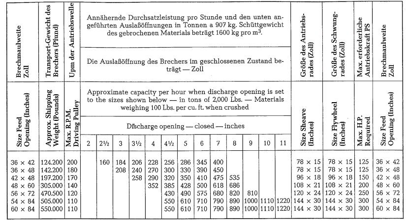
The following table contains information concerning jaw crushers of United States origin [40].
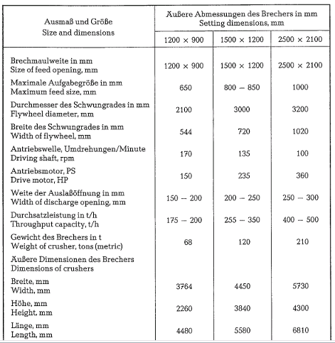
The following table contains data about crushers manufactured in the Soviet Union (Ural Machinery Plant UZTM) [41].
Cone Crushers
Gyratory crushers (known also as cone crushers), crush the material between the cone shaped station ary crushing ring and a crushing cone; the cone per forms a gyratory motion about a vertical shaft, the lower end of which is positioned in an eccentric. The size reduction is performed mainly by compression and partially also by flexural stress, but generally in the same way as in the jaw crusher. These crushers are manufactured in two types:

Gyratory crushers, called also Gates-crusher (Fig. 3.13.), in which the positions of the crushing cone and the conical crushing ring oppose each other, and Cone or Symons-crusher (see Fig. 3.14.), in which the position of the crushing cone and the conical crush ing ring are adjacent to each other.

Gyratory crusher
The structural design and the working principle of a gyratory crusher are shown in Fig. 3.15. The main parts of this crusher are: The stationary conical crushing ring (1), the mobile crushing cone (2) mounted on the main crusher shaft (3). The main shaft with the crushing cone is oscillating suspended from a ball and socket joint located in the upper crusher housing (spider). This is the characteristic design fea ture of the gyratory crusher. A bevel wheel (6) driven eccentric (5) in which the lower part of the main shaft is located, causes the crushing cone to perform its gyratory motion.

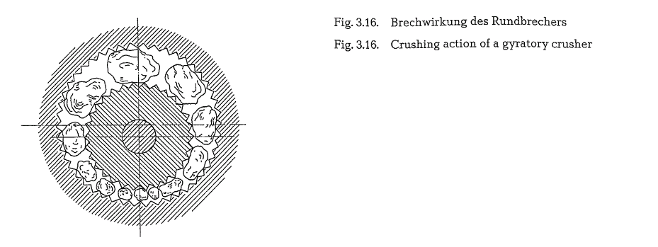
The angle between the vertical and the crusher shaft is equal to 2-3°. In this way the shaft mounted crushing cone approaches and recedes periodically from the stationary conical crushing ring. This causes pressure on the material trapped between the two cones, thus effecting size reduction. It should be mentioned that the crusher shaft does not rotate about its own axis. The crushing action of both cones of a gyratory crusher is schematically shown in Fig. 3.16.
Number of revolutions:
The formula for the optimum number of revolutions for the main shaft of a gyratory crusher is similar to that for the rpm of the swing jaw drive of a jaw crusher and reads
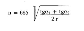
The same formula adjusted somewhat by practical experience, reads as follows
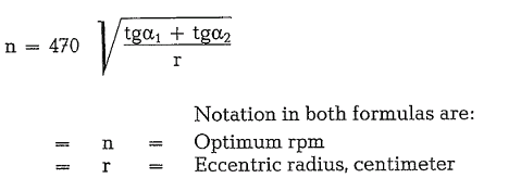
a.1 and a.2 is the total of angles between the crushing ring and the vertical and between the crushing cone and the vertical, as shown in Fig. 3.17. The total of these angles is approximately 20-23°.

Capacity
The capacity of a gyratory crusher can be estimated by employing Giesking’s formula (see section 3.5.), which is also applicable to jaw crushers.
Example 3.5.
Data given: Non-prescreened limestone withy = 1.7; opening of the crusher slot is 150 mm; diameter of crusher slot is 1800 mm, thus perimeter of discharge opening 180 em · n = 565 em. Crushing ring and crushing cone are not ribbed, c = 1.4 · 10-4. Number of strokes is 150/min. Angle between crushing ring and crushing cone is 26°, thus b = 1.-; amplitude of cone (eccentric) is 3.75 em, and 11 = 0.85.

Size designation of gyratory crushers
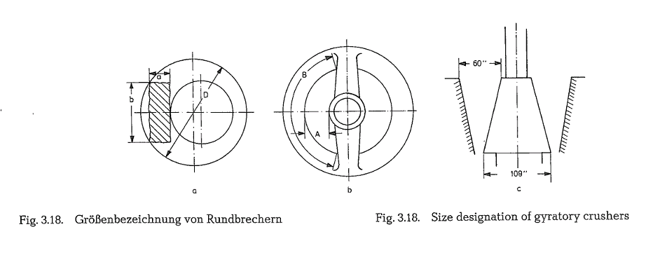
The size designation of gyratory crushers is inconsis tent. In the Soviet Union, the feed opening A (see Fig. 3.18. b) is used as the size designation. In Germany, the crusher size is designated by the diameter D of the crushing ring (see Fig. 3.18. a); sometimes the dimension A is added to this. In the United States the crusher size is designated by A · B, as shown in Fig.3.18. b
Another numerical size designation of gyratory crushers represents the feed opening and the maxi mum diameter of the crushing cone as e. g. 60- 109 inches (see Fig. 3.18. c). For the comminution of crusher feed of the size a · b (Fig. 3.18. a) by a jaw crusher, a feed opening of 1.25 (a · b) is required. However, for the same feed size, a gyratory crusher needs a feed opening which is much larger.
Adjusting of the discharge slot
To compensate for wear of the crusher lining and to reset the discharge slot to its original width, or to change – when required – the crusher’s product size, a vertical adjustment of the main shaft in the range of 150-280 mm is possible, depending upon the size of the crusher.
This can be achieved:
- By positioning a split nut in the proper location on the upper threaded portion of the main shaft sus pended in the spider hub; this is a tedious opera
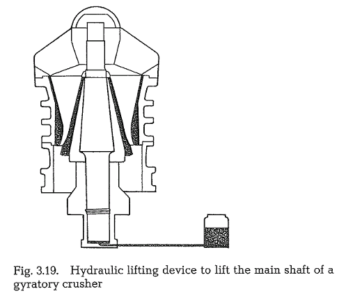
- By a hydraulic lifting The main shaft assembly is supported on a hydraulic jack. When oil is pumped into the jack, the main shaft is raised (Fig. 3.19. a), and vice versa; when oil is removed from the jack, the main shaft is lowered. This is a one minute operation.
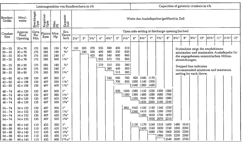
The following table contains capacities expressed in tons per hour {2000 lb per ton) of gyratory crushers manufactured in the United States [42], based on a bulk density of 100 lb per cubic foot of crushed material.
General characteristics
The cement industry employs gyratory as well as jaw crushers mainly as primary crushers. Compared to the jaw crusher, the gyratory crusher has a two to three times higher capacity with the same sizes of feed opening and discharge slot. The gyratory crusher does not perform idle motions and works continuously during the gyration of the crusher’s main shaft. On the basis of energy consumption, the capacity of a gyratory crusher per kWh is 1.3 to 3.6 times higher than that of a jaw crusher. For crushers of medium size this factor is 1.3 to 1.4 and for large crushers the capacity factor is 2.1 to 3.6. This leads to the use of gyratory crushers for large size crusher feed. When idling, gyratory crushers use up only about 30 % of the full load energy, whereas for jaw crushers the figure amounts to 45-50 %. In gyratory crushers lamellar or needle-shaped product is almost absent. On the other hand the wear of liners is higher than that of jaw crushers. Liners in gyratory crushers have to be replaced more often than in jaw crushers. Also the reversal of the liners performed in jaw crushers is impossible in gyratory crushers. The reduction ratio of gyratory crushers is 7 : 1 to 15 : 1. The capacity of gyratory crushers amounts up to 5000 t/h, at a width of the discharge slot of 12 inches (see capacity table). The gyratory crusher does not need a special feeder; the crusher feed can be discharged from any means of transportation (mostly rear dump trucks) directly into the crusher’s feed opening.
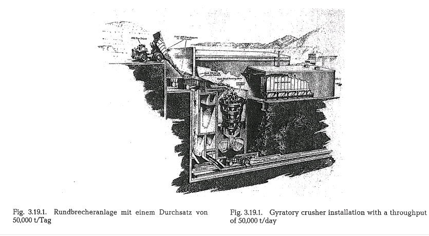
Fig. 3.19.1. (Fuller Co.) is a cross-section drawing of an underground installation of a gyratory crusher which gives a visible imagination about the size of such crushing arrangment. In this case instead of lime stone, copper ore is crushed. The gyratory crusher shown here has a throughput of 50,000 t/day, and is fed by 100-200 t capacity rear dump trucks. In this case the material is conveyed to the crusher by vibrating grizzly feeders to remove undersize particles. This Fuller Co. installation is located in Butte, Montana,USA.
Cone or Symons-Crusher
For this type of crusher the positions of the crushing cone and conical crushing ring are arranged with each other as shown in Fig. 3.14. These crushers are mainly employed as secondary crushers.
Compared with the gyratory crusher, the basic differ ence is that the main shaft of the cone crusher is not designed as a suspended mechanism but is fastened at its lower end in the eccentric. The upper end of the crusher shaft is intended to serve as the crusher feed dispersion table. From the dispersion plate the mater ial is directed into the crushing compartment where comminution is performed by compression between the surfaces of the two crushing cones; simulta neously the material moves towards the direction of the discharge slot, as is shown in Fig. 3.20. The dist ance of the surfaces of the two crushing cones decreases in the direction to the discharge slot.

From Fig. 3.20. it can be seen that both crushing cones form a parallel discharge slot; the length of this slot is denoted as l, and the shortest distance of both cones is marked as d. To achieve a reduction of the crushed material to the size d, every crushed particle must pass the discharge slot through the slot’s smallest dimension. This means that the time of passage of each crushed particle along the length l of the slot must not be less than required for one full revolution of the crushing cone around its eccentric. This condition requires crushing cone speeds higher than those of gyratory crushers.
Size designation
The size of cone crushers is designated by the diame ter of the base of the crushing cone; see dimension D in Fig. 3.20.
Rotary speed of the crushing cone
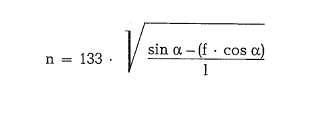
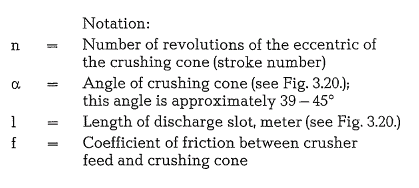
To calculate the optimum number of revolutions of the eccentric sleeve, i. e. the number of strokes of the crushing cone, the following empirical formula can be employed [39]:
Example 3.6.
Calculate the stroke number of the shaft of a cone crusher; a = 41, the coefficient of friction f = 0.3, l = 0.13 meter.


Drive energy
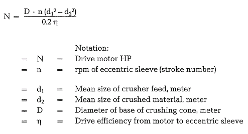
The drive energy for a cone crusher is determined by the following formula:
Example 3.7.
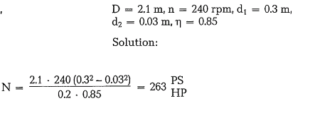
The following figures are available for calculating the motor size of a cone crusher:
Capacity
The capacity formula for the cone crusher is
![]()

Example 3.8.
The following figures are available for calculating the capacity of a cone crusher: D = 1.65 m, d2 = 15 mm
= 0.015 m, n = 240 rpm, andy = 2.6 tons per cubic meter.

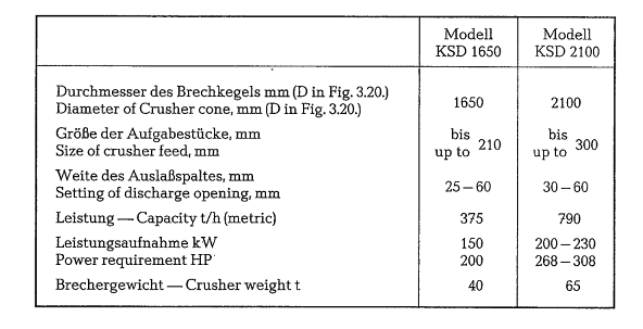
The following table contains information about cone crushers of Soviet manufacture (Ural-Machinery Construction Plant UZTM) [44].
Roller crusher
Comminution in a roller crusher is based on the pas sage of material between two rotating rolls which crush the material by compression. The particle size of the crushed material depends on the distance of both rolls from each other. Depending on the kind of crusher feed, the surface of the crushing rolls can be smooth, ribbed or toothed. Subject to the hardness of the crusher feed, the ribs can be arranged along or across to the axis of the rolls.
Fig. 3.21. shows the configuration and working method of a roller crusher. One of the crushing rolls
(1) is rigidly installed in the crusher frame (2), whereas
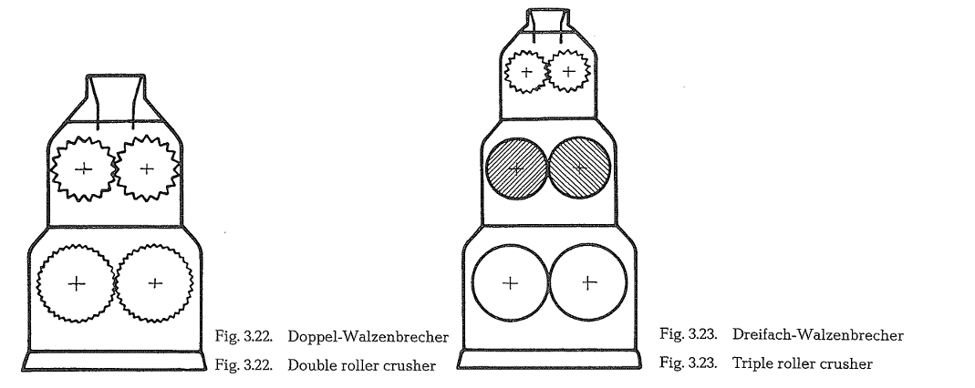
the other roll slides horizontally under spring pres sure. The elastic springing (3) of one of the rolls is a safeguard against unbreakable material (digger teeth, tramp iron, etc). To prevent friction between crusher feed and the rolls, both crushing rolls have the same speed of rotation. The drive is off a motor through a V-belt sheave (4), and a gear wheel (5) to the fixed roll, and through a suitable linkage to the sliding roll. There are also designs with each roll being individually driven by a separate motor. If one pair of rolls is employed, the reduction ratio is from 1 : 5 to 1 : 7. To gain a higher reduction ratio in one roller crusher,ie. to avoid the use of two separate crushers, two pairs of crushing rolls, arranged one above the other, are in use (double roller crusher); in doing so, the upper pair of rolls serves as a primary crusher, where the lower pair functions as a secondary crusher. Also, triple roller crushers for special crushing operations are manufactured.
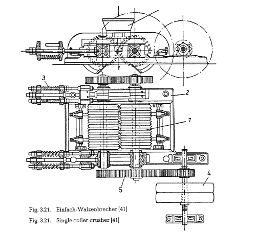
Fig. 3.22. shows the arrangement of a double roller crusher, and Fig. 3.23. represents a triple roller crusher.
Frequently the cement industry also employs roller crushers for the size reduction of coal, used as fuel in rotary drum driers.
Capacity
The throughput capacity of a roller crusher can be determined using the following formula:


Example 3.9.
Use the given formula to determine the throughput capacity of a roller crusher; the following figures are given:
D = 1.0 m, L = 0.8 m, n = 65 rpm, d = 0.012 m, and y= 1.68 t/m3.

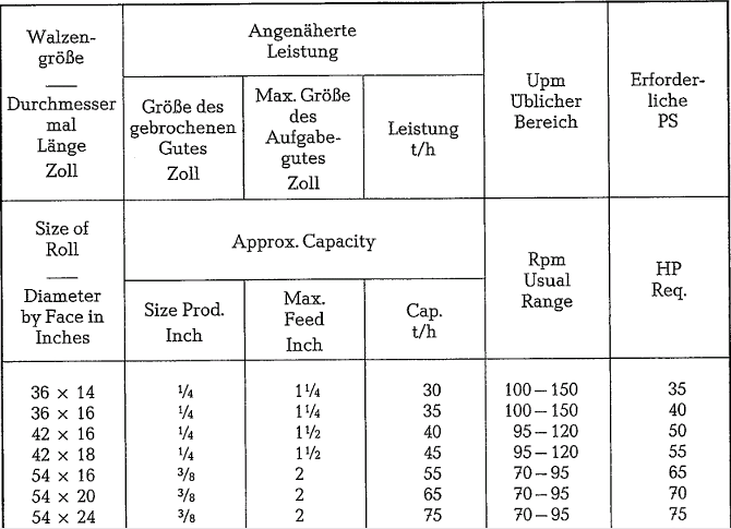
The preceding table contains specifications of roller crushers of American manufacture [45].
Capacities are based on material with a bulk density of 100 lb per cubic foot after crushing. The HP-figures in the table refer to average capacities only, and are based on medium hardness of the crusher feed
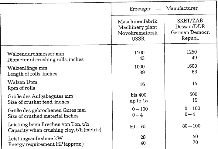
The following table contains capacities of roller crushers with toothed rolls [46].
Hammer crusher
Hammer crushers are widely used in the cement industry. They are used for size reduction of hard to medium hard limestone, and sometimes for marl crushing. Hammer mills work with reduction ratios as high as 1 : 60; depending on the crusher feed, this ratio can increase to 1 :80. Sometimes the high reduc tion ratio of hammer crushers does away with the need for the installation of multi-stage crushing plants. Generally two types of hammer crushers are manufactured: single shaft and double shaft hammer crushers. These crushers work with the impact effect of the hammers according to the formula for the kinetic energy or impact (P):

Starting from this point the mass of the hammers in hammer mills was reduced to a minimum while at the same time increasing the velocity v as far as possible. The result was greater impact force combined with reduced wear.
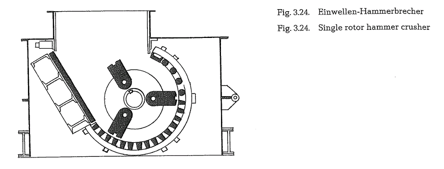
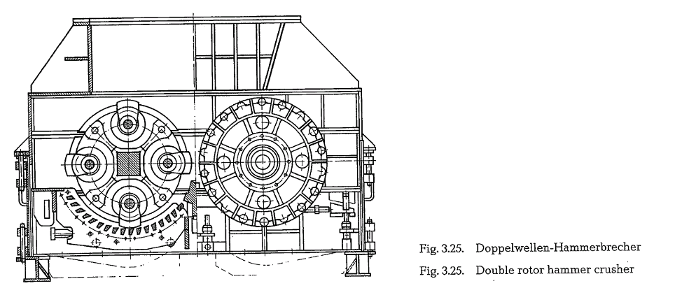
Fig. 3.24. shows a schematic of a single rotor hammer mill.
Fig. 3.25. shows a double rotor hammer mill. (Titan crusher of the Orenstein and Koppel AG, Germany).
The Biihler-Miag Co. sold the manufacturing rights of the Titan-crusher to the Orenstein and Koppel Co.
In both types of crushers the crusher feed first passes through to upper or primary grid; this follows preliminary size reduction of the material by the impact hammers. The final crushing then occurs on the bars of the lower grid. Because of the two grids with differ ent spacings, the hammer mills can be considered two stage crushers. An adjustment of the grid spacing controls the final particle size; the final particle size is approximately equal to one half of the grid spacing. The grid spacing of the lower grid is generally 25- 30 mm. Higher moisture content of the crusher feed requires larger spacings up to 60 mm. Depending on the requirements, a spacing of 200 mm can also be applied. Moist and sticky crusher feed requires trian gular grate bars; otherwise trapezoidal bars are in use.
Since the primary grid sometimes caused operational disturbances, new models of hammer crushers are build without this grid.
The impact of the hammers upon the crusher feed is not even; this means the load upon the crusher and the drive motor is not continuous. Massive flywheels are used to stabilize the operation. The double rotor crusher has separate drive motors for each shaft.
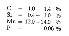
The weight of the replacable impact hammers is in the range of 20 to 200 kg each, depending upon the crusher size. The chemical composition of the hammer steel is:
Depending upon the hardness of the crusher feed, the specific wear of the impact hammers is 1.5 to 3.0 grams per ton of crushed material. The wear rate of Cr-Va-steel is 3 grams and that of Cr-Si-Va-steel was estimated to 2 grams per ton of crushed material [47].
The rim speed of the hammers is in the range of 25 to 50 m/s.
The number of revolutions of both the single and double rotor crushers is in the range of 250- 400 rpm, depending upon the crusher size.
The power demand of single rotor crushers is between 1.3-2.8 HPh/t; double rotor crushers have an energy demand of 1.8-2.5 HPh/t of crushed material.

Fig. 3.26. shows six different design modifications of impact hammers for hammer mills [47a].
To estimate the throughput capacity of a hammer breaker for limestone, the following empirical for mula was developed:

Example 3.10.
Estimate the capacity of a hammer breaker; D meter, L = 1.3 meter.

Assuming a bulk density of the crushed limestone of 1.6 t/m3, the capacity expressed in tons is
88 . 1.6 = 140 t/h
The required power input can be calculated using the following formula:

Another, more precise formula for the derivation of the required power input reads:

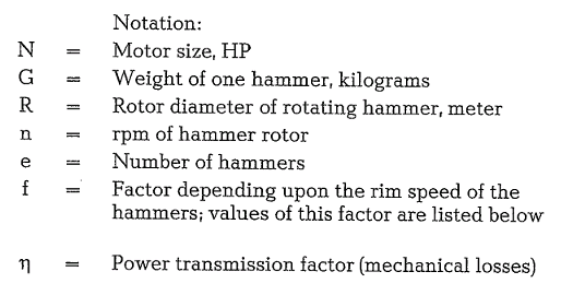
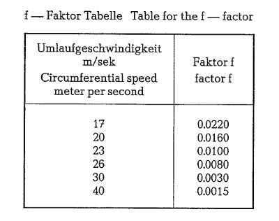
Example 3.11.
Estimate the required power input for a double rotor hammer crusher with 2 x 16 hammers; weight of one hammer is 30 kg; speed of rotors is 250 rpm, rotor diameter is 1.0 meter, and power transmission factor is 0.85
Solution:
The rim speed for determining the £-factor is

From the preceding table the £-factor for 26 m/s is 0.008. Thus the required drive energy for both motors is

Hence, two motors with 88 HP or 65 kW each should be provided; the next higher available motor size should be selected.
Fig. 3.27. shows a standard arrangement of a crushing plant with a double rotor hammer crushing (Oren stein and Koppel AG, Ennigerloh, W. Germany).
Fig. 3.28. shows a two-stage crushing plant for pri mary and secondary crushing, equipped with high capacity double rotor hammer crushers (Orenstein and Koppel AG, Ennigerloh, W. Germany).


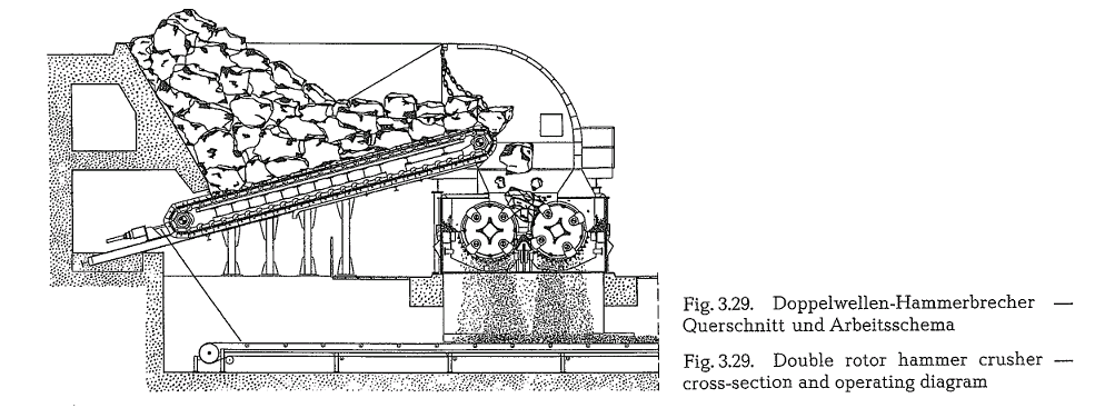
Fig. 3.29. shows the cross-section and the operating diagram of a double rotor hammer crusher in stan dard design (Orenstein and Koppel AG, Ennigerloh, Germany).
The following table contains technical data for the 0 + K double rotor hammer crusher “Titan” for crush ing capacities from 220 to 2000 metric t/h.
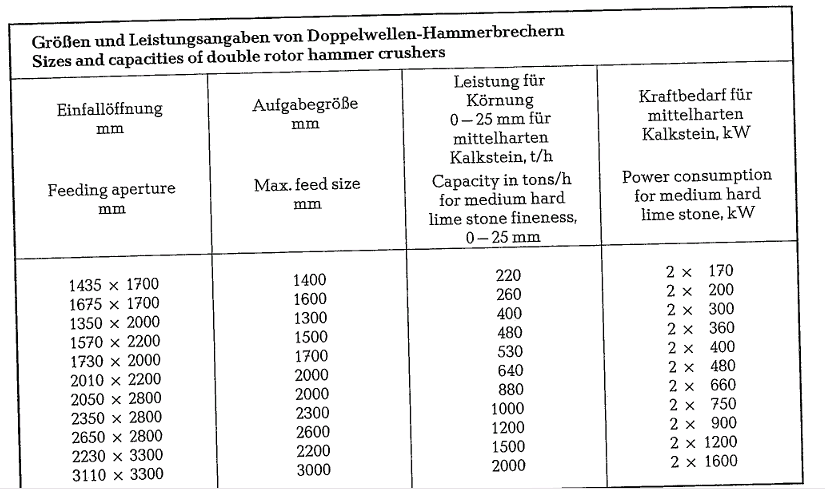
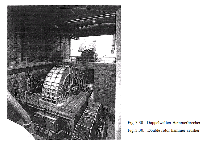
Fig. 3.30 shows a complete crushing plant equipped with a double rotor hammer crusher “Titan”, manufac tured by Orenstein and Koppel AG, Ennigerloh, W. Germany.
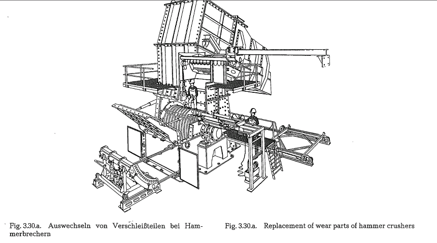
For replacement of wear parts the manufacturers of single and double rotor hammer crushers supply also electrical and hydraulical auxiliary equipment as e.g. grate cage extractors, hammershaft renewal arrange ments or auxiliary cranes (see Fig. 3.30.a.) [255a].
The equation for the kinetic energy of the hammer, quoted at the beginning of this section, is only one of the basic physical equations for the explanation of comminution processes, when applying size reduc tion machinery working by impact. The dynamic con ditions of the hammer and the comminution stress of the rock are complex, and hard to comprehend; therefore, an exact calculation of the stress condi tions is difficult. Based on a simplified physical con ception, supported by proper measurements, an effort was made to develop equations for the description of the dynamic conditions. The following equations were developed:
- Equation for the hammer efficiency
- Equation for the effective comminution capacity
- Equation for the size of the drive motor
On the basis of these findings, the KHD Humboldt Wedag AG, W.Germany, designed its hammer crush ers. The following table contains capacity data of these hammer crushers.
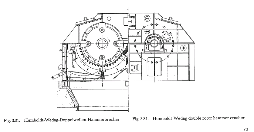
Fig. 3.31. shows a cross-section of the Humboldt Wedag double rotor hammer crusher.
The material crushed in double rotor hammer crush ers is limited to certain characteristics of its properties. These limits are (according to KHD Humboldt WedagAG):
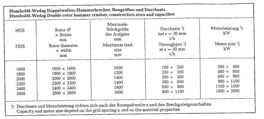
ties. These limits are (according to KHD Humboldt WedagAG):

When operating a one-rotor hammer crusher, the moisture content of the crusher feed should not exceed 10 %; the clay content is limited to 20 %. Also the wear rate is limited for both types of crushers. The expected specific net wear rate of the hammers should not exceed 5 grams/t (metric).
Impact crusher
Crushing by impact is a dynamic operation. Size reduction by the impact crusher ensues in three pro cedures. The first procedure, i.e. the main size reduc tion is carried out by striking, i.e. by impact of the impeller bars to the crusher feed. The purpose of the breaker plates arranged inside the crusher, is to func tion as deflecting plates; the material thrown against them, is reflected back into the crushing compart ment, where it is again hit by the impeller bars, until it leaves the crusher through the slot between rotor and the lower edge of the breaker plate. The second size reduction process is carried out by impact of the material against the breaker plates. The third size reduction step occurs by crashing of the material chunks against each other. However, in this system the predominant component of size reduction is the effect of impact. The breakage or size reduction fol lows along natural cleavage lines, i.e. where cohesion is low. Thus, crushing by impact can be applied only to brittle rocks, since plastic material does not shatter when impacting against breaker bars or plates.
Impact breakers consist of one or two impellers which are supplied with impeller bars. The circumfer ential speed of the impellers is approximately 24- 45 m/s. This speed is necessary to impart the required velocity on the crusher feed. Thus the size reduction energy depends on the circumferential speed of the impeller. Each kind of rock requires an appropriate circumferential speed to get the maximum through put with the most advantageous particle size. Low cir cumferential speed generates coarse particle sizes, and vice versa. The specific energy consumption is 0.6- 1.4 HPh/t. The total steel wear is in the range of 0.3- 3 grams/t throughput; this includes the impeller bars, the breaker plates and the breaker bars. The steel wear depends directly on the rotor’s circumfer ential speed; the wear increases with the square of the circumferential speed [47i].
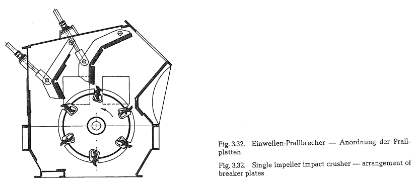
In a single impeller impact crusher the breaker plates are arranged in a suitable distance around the impeller, at it is shown in Fig. 3.32. (Hazemag Bulletin EH 1236087).
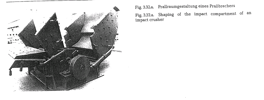
The shaping of the impact compartment is very important for the comminution behavior of different materials. Therefore, the Orenstein & Koppel Co. developed impact walls and impact trajectories which render almost each shape of crushing space. Impac tors can be exchanged to adjust the crushing space to the crusher feed as well as to the desired material discharged by the crusher (see Fig. 3.32.a. – Oren stein & Koppel [0 +K] AG).
Fig. 3.33. shows another arrangement of the impeller and the breaker plates. This crusher is also supplied with breaker bars.
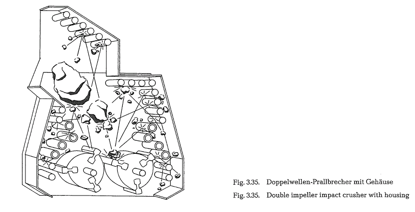
Fig. 3.34. shows the impact action of a double impeller impact crusher.
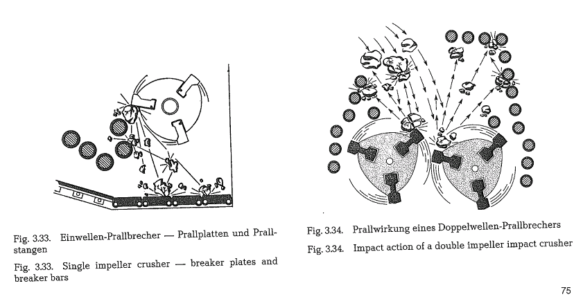
This impact crusher is equipped only with breakeJ bars on which the rocks are dashed into pieces. Then are no breaker plates. The breaker bars do not act al a grid. They are part of the size reduction system. ThE degree of size reduction of double impeller crushen depends on the measuring point in the particle sizE diagram. It is in the magnitude of 1:40 to 1:50
Fig. 3.35. shows a double impeller impact crusher witl housing (Fig. 3.33., 3.34 and 3.35.: Iowa Manufacturin Co., Bulletin DI-1).
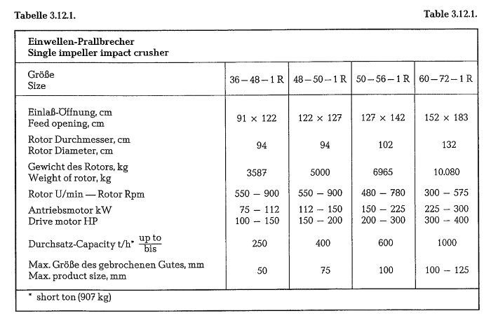
The breaker bars have replaceable manganese sleeves which can be easily replaced after they are worn out by use.
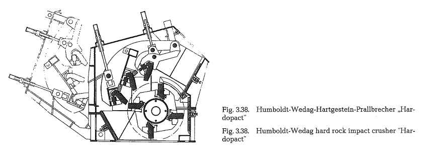
Rocks of extreme hardness are rather difficult to comminute in an impact crusher. Reduction of such rocks in conventional impact crushers requires high maintenance and operating costs, which in this case is uneconomical. For such cases, the Humboldt Wedag Hardopact crusher was developed (see Fig. 3.38.). Likewise conventional size reduction machi nery such as jaw crushers, gyratory crushers, and under certain conditions, also hammer crushers, are appropriate and economical.
Table 3.12.1. contains sizes and capacities of single rotor impact crushers (Kennedy Van Saun, York, Pa. USA, Bulletin 663).
For practical determination of the motor size for an impact crusher, the KHD Humboldt Wedag AG developed the following formula:


KHD Humboldt Wedag AG manufactures three dif ferent types of impact crushers, namely:
The coarse impact crusher PEG,
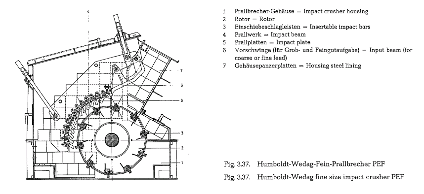
The fine size impact crusher PEF, and
The hard rock impact crusher ..Hardopact”.
The following illustrations 3.36., 3.37. and 3.38. show cross-sections of the three above quoted impact crushers.
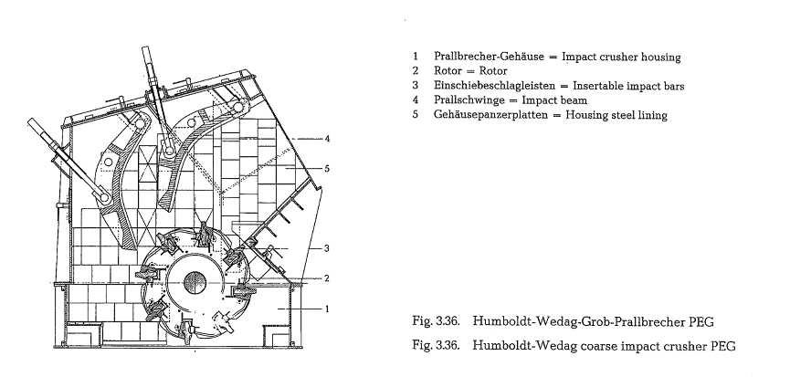
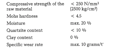
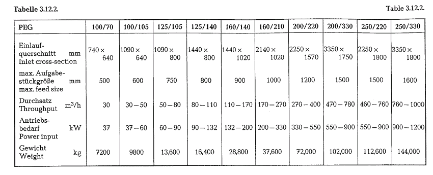
Coarse impact crusher PEG: This impact crusher is mainly applied for the first stage of comminution of cement raw materials such as limestone, chalk, gyp sum, coal, etc., from a maximum feed size of 1600 mm edge length, down to a product size of 0- 150 mm at a capacity of 1500 metric t/h. Table 3.12.2. contains con struction sizes and capacities of the PEG coarse impact crusher. It should be mentioned that the capa city and the necessary drive power depend on the characteristics of the crusher feed and on the required product size.
The size reduction work of impact crushers is limited to certain quality characteristics of the crusher feed. For the PEG coarse impact crusher these quality limits are:
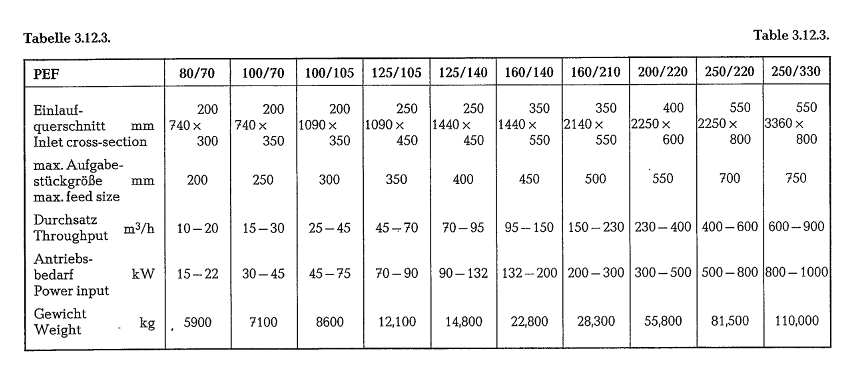
Fine size impact crusher PEF: The main domain of application of the PEF impact crusher is the fine size reduction of cement raw material and coal, from a feed size of maximum 750 mm edge length to a prod uct size of 0-45 mm, at a capacity of 1400 metric t/h. Table 3.12.3. contains construction sizes and capacity data of the PEF fine size impact crusher. Also with this crusher, the capacity and the necessary power input depend on the characteristics of the crusher feed and on the requirements concerning the product size.
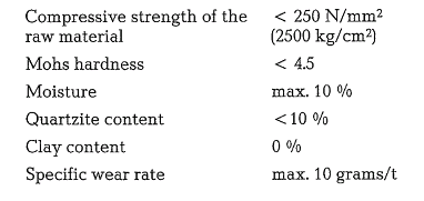
The limits of application of the PEF fine size impact crusher are:
Hard rock impact crusher ‘Hardopact”: For hard and stabile rocks, the manufacturer developed a special hard rock impact crusher, which is on the market since 1965. In the cement industry, the application of the hard rock impact crusher is for size reduction of iron ore and quartzite as corrective ingredients for the proper cement raw mix composition; also commi nution of slags can be economically performed with this impact crusher.
Generally, this crusher is qualified for size reduction of rocks with high degrees of Mohs hardness, with compressive strengths above 250 N/mm 2 (2500
kg/cm2), and high Si02-contents. This crusher is man
ufactured in six sizes. Its scope of work lies between 400 mm feed size, and 0-35 mm product size; the capacity range is from 50-240 metric t/h.
When using a 2-zone impact arrangement the throughput can be increased (depending on the con struction size), from 65 t/h to 320 t/h, if the high prod uct quality of the granulometric composition (cuboi dal shape, compressive strength) of the customary 3-zone impact crusher are not required. This results in a higher weight as well as in a higher power requirement.
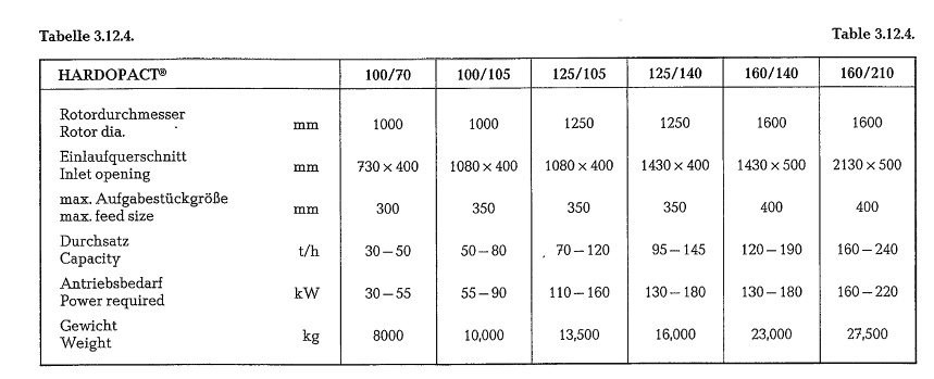
The manufacturer claims the following special pro perties of this crusher: low wear rate and low energy cost, due to the low circumferential speed of the rotor, which is within the limits of 22-30 m/s. The following table contains construction sizes and capa city data of the Hardopact impact crusher [47j, 47k, 471, 47m].
The limits of application of the Hardopact impact crusher are:

Compound impact crusher
The Compound Impact Crusher (manufacturer Hazemag KG, 44 Munster, Westfalia, West Germany) is so named because it combines two types of crushers in one housing. The crusher housing contains an arrangement of two parallel running impellers. Primary and secondary impellers are equipped with impact bars. As is shown in Fig. 3.39. the secondary impeller is arranged on a lower level than the primary impeller.
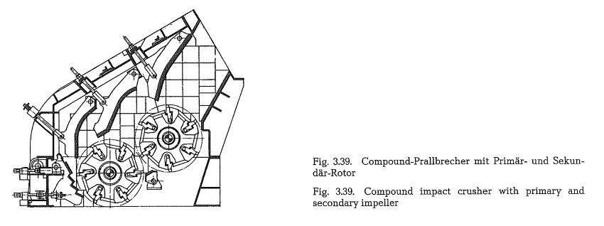
It was found that the position of the impellers to the horizontal is of major importance. With this com pound-crusher it is possible to attain a degree of reduction from 1 : 60 to 1 : 70.
Quarried rocks of about 1500 mm side length can be crushed in one pass to a final particle size of 95 % minus 1 inch. The primary impeller is for primary crushing, whereas crushing to final particle size is performed by the secondary impeller. The circumferential speed of the impellers is between 35 and 45 m/ s, depending on the characteristic of the crusher feed.
Impact-hammer crusher
This crusher (manufactured by F. L. Smidth, Copen hagen, and called EV-Crusher) is a combined impact and hammer crusher. The EV-hammer crusher is sup plied with an adjustable jaw plate and with an adjust able discharge grate. The limestone supplied from the quarry is crushed in a single operation to a finished
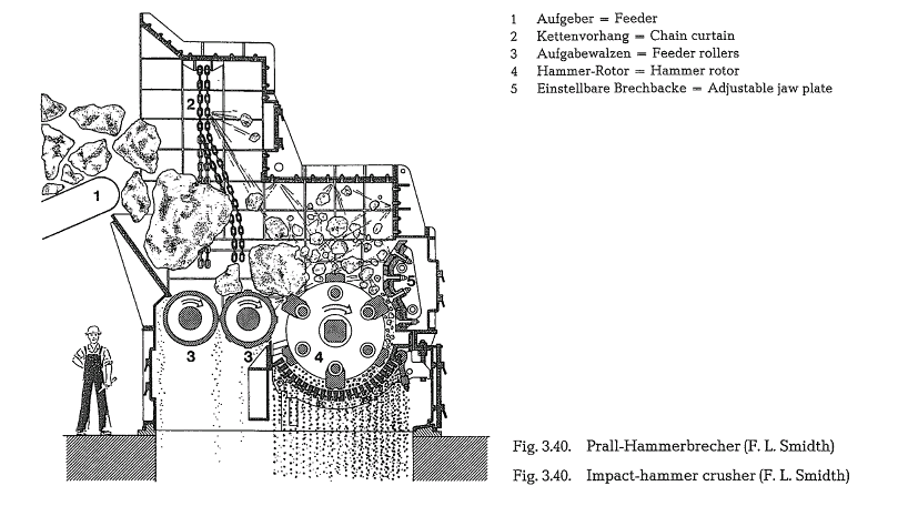
product oL 95 .% minus 1 inch. Fig. 3.40. shows a cross-section of an EV-hammer crusher.
The hammer crusher can be fed with rocks of 1-2 m3 size, with an edge length of up to 2 m. The feed falls upon two slowly rotating shock-absorbing rollers transporting the material to be crushed, to the crusher proper. The slot between the two rollers serves for scalping of the undersize fraction from the crusher feed. The hammers which are suspended in through-bolts, rotate at a circumferential speed of 38-.40 m/s; the weight of the hammers is in the range of 90- 250 kg per unit.
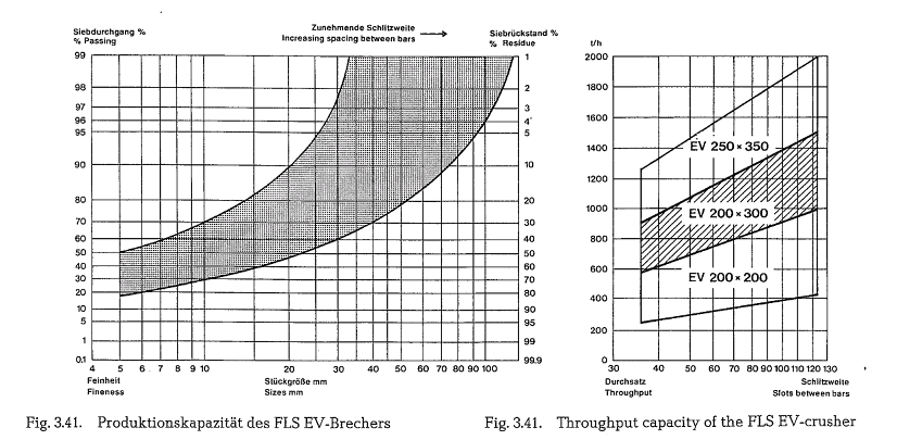
By adjusting the jaw plate, the discharge grate, as well as the spacing between the grate bars, the size of the crusher product can be selected; this, of course, results in variations of the crusher’s capacity. This is graphically shown in the EV-crusher capacity dia gram (see Fig. 3.41.).
According to the manufacturer, the specific power requirement of the EV-crusher for particle size reduction to a fineness of 95 % minus 25 mm, varies in the range of 0.9-1.1 kWh/metric ton