Contents
click here to download Holcim , fls smidth , Lafarge , Most importnant manuals , most important excel sheets
click here to download Holcim , fls smidth , Lafarge , Most importnant manuals , most important excel sheets
Types of Rotary Kilns
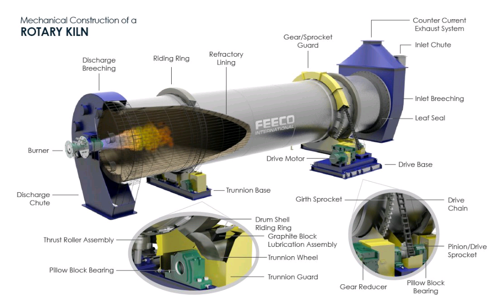
Generally speaking, the clinker manufacturing processes used in rotary kilns are classified into:
-Wet-Process Kilns
-Semidry Kilns
Dry Kilns
-Preheater Kilns
-Precalciner Kilns
Each of these types are discussed here.
WET PROCESS
Into this group fall all processes in which the kiln feed enters the kiln in the form of a slurry with a moisture content of 30 to 40%. In comparison with a dry-process kiln of the same diameter, a wet-process kiln needs an additional zone (dehydration zone) to drive off the water from the kiln feed. Therefore, it must be considerably longer in order to achieve the same production rate.
To produce an equivalent amount of clinker, a wet-process kiln requires theoretically more .fuel than a dry-process kiln because of the extra heat required to evaporate the water. However, in actual operation of a kiln this fundamental fact does not always hold entirely true. As one progresses in the reading of this book, the reasons for these discrepancies between theory and actual operation will become clearer and understandable.
Advantages of a wet-process kiln are:
- feed is blended more uniformly than in the dry process
- dust losses are usually smaller, and
- in moist climate regions, wet processing of the raw material is more suitable than dry because of moisture already present in the blend materials.
SEMIDRY PROCESS
This member in the group of rotary kilns is also widely known under the term Grate Process Kiln or Lepol Kiln. These kilns are as efficient in matters of fuel consumption as the most modem preheater and precalciner kilns. Output rates, however, lag behind the aforementioned types of kilns. However, it is advantageous to select a Grate Process Kiln over a preheater or precalciner kiln in places where raw material moisture is so high that it cannot be economically dried by waste heat from the kiln. Lepol Kilns, because of the fact that the kiln exit gases pass through the granular feed bed, operate with much lower dust contents in the waste gases which gives these kilns a decisive advantage over other preheater kilns. Instead of granulating the kiln feed, some plants use filter press cakes to feed the kiln. In such cases, the wet-kiln feed slurry is first passed through large presses for removal of the free water and more importantly, to remove alkalies before the filter cakes are fed to the kiln.
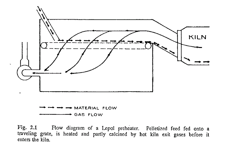
In the grate process, pulverized dry-kiln feed is first pelletized into small nodules by means of 10-15% water addition, then the nodules are fed onto a traveling grate where they are partly calcined before they enter the rotary kiln. Heating of the nodules is effected by the exit gases from the rotary kiln, the hot gases passing through the material bed from above as they are drawn downward through the grates by means of a fan. The partly calcined material then falls down a chute into the rotary kiln where final clinkerization takes place. Because the kiln feed is already partly calcined before it enters the kiln, the rotary kiln itself is only about one-third the usual length. Fig. 2.1 is a schematic diagram of the flow of gas and material through a Lepol grate-process preheater.
One advantage of grate-process kilns is the uniform size of clinker leaving the kiln, an aspect that is decidedly beneficial for grinding the clinker. However, there are some features not found in conventional rotary kilns that need very close attention; for example, production of the nodules and control of the thickness of the feed bed over the traveling grates. Such a kiln usually requires additional labor to attend the granulator plant.
DRY-PROCESS KILNS
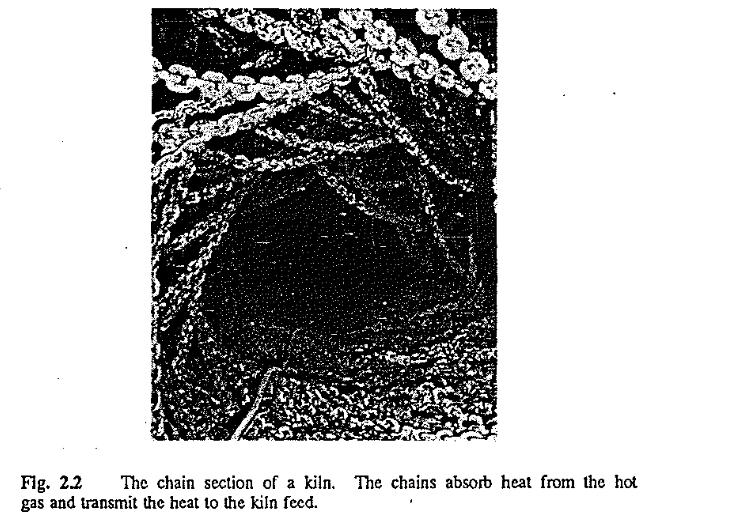
As the term indicates, in this process the kiln feed enters the kiln in dry powder form. Dry-process kiln dimensions are similar to wet kilns in that they are long and typically show a length-to-diameter ratio of approxi mately 30:1 to 35:1. Dry-process kilns operate with a very high, back-end temperature and require watersprays at the feed end to cool the exit gases to safe levels before they enter the baghouse or precipitator. Most dry kilns are equipped with chain sections at the feed end to transfer heat, that other wise would be lost, to the feed before the gases leave tl1e kiln.
Fig. 2.2 shows a picture of a chain section. The gases enter the chains at a temperature of approximately 800 C (1470 F) and leave tl1e kiln exit at a temperature of 450 C (840 F). In countercurrent flow, the material enters the chains with a temperature of 50 C (120 F) and emerges from the chain section with a temperature of 730 C (1350 F). Chain sections are a high maintenance item; difficult to repair but an absolute necessity for efficient operation. Because of the high costs of these chains, there is a tendency in many plants to neglect proper and frequent maintenance. How ever, i_t has been found in many instances that the costs saved, by not tak ing care of the chain system, are coming back manyfold in the form of higher fuel operating costs.
There is an advantage found in dry kilns that none of the other kiln types exhibit The high exit-gas temperature on these !dins renders them perfectly suitable for cogeneration of electrical power. As a matter of fact there are several plants with dry kilns that generate their own power and many existing plants are taking a hard look at the feasibility of adding a power plant to their facility. The reasoning is simply that generating power is energy-conserving and in some locations it may be more economical to add a power plant to an existing dry kiln than to convert this kiln to preheater status.
THE PREHEATER KILN
In the gas-suspension preheater kiln, the dry feed is preheated and partly calcined by the hot kilh exit gases in a tower of heat exchange cyclones. This concept is, contrary to popular beliefs, not new because a patent on this type of kiln was issued in Czechoslovakia already in the early 1930’s. However, the suspension preheater kiln as it is known today did not come into its own right until after World War II when German kiln manufacturers were able to overcome the operational and structural problems of these types of kilns (Fig. 2.3).
The preheating of the kiln feed is done outside the rotary kiln proper, i.e., before the feed enters the kiln. The heat exchange between the gas and the material takes place in the cyclones while both are in suspension. Many different designs of preheater towers are in existence using this basic principle. The most common design is the parallel four-stage preheater. Some of these can reach output rates of up to 8000 metric tons per day. Exit gas temperatures leaving the top # 4 stage are around 340 C (640 F) and in many such plants, these waste gases are used (together in some cases with tile waste gases from the clinker cooler) for drying and preheating of kiln feed in the raw grinding department. One drawback of preheater kilns is the high concentration of volatile constituents such as alkalies, sulfur, and chlorides in the kiln exit gases that give tise to numerous plug-up problems at the lower cyclone stage and kiln inlet. For this reason, most suspension preheater kilns must be equipped with an alkali and sulfur bypass that allows evacuation of a percentage of the kiln exit gases and thus bypasses the preheater cyclones. Such bypasses are not only used for reducing plug-up problems but in many plants are a neces· sity to keep the alkali content in the clinker below maximum permissible levels.
Suspension preheater kilns are the most energy-efficient types of kilns available operating typically witl1 a specific fuel consumption of around 3138 MJ/ton clinker (750 kcal/kg, 2.7 MBtu/sh.ton).
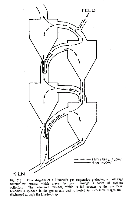
Fig. 2.3 Flow diagram of a Humboldt gas suspension preheater, a multistage counterflow process which draws the gases through a series of cyclone collectors. The pulverized material, which is fed counter to the gas flow, becomes suspended in the gas stream and is heated in successive stages until discharged through the kiln-feed pipe.
THE PRECALCINER KILN
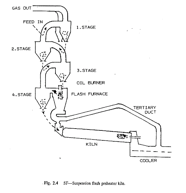
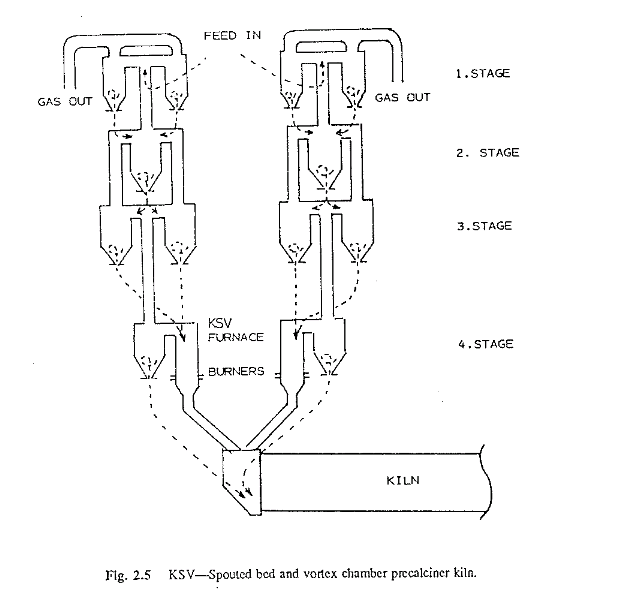
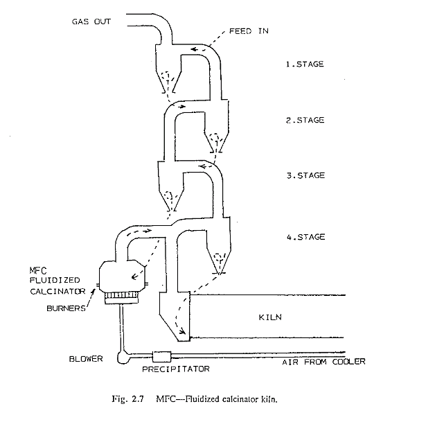
Roughly 15 years ago, Japanese cement manufacturers were confronted with the question of how best to increase the production rates of existing preheater kilns. As mentioned earlier, their preheater kilns reached limits in dimensions that gave rise to considerable operational and structural design problems. These kiln diameters became so large that refractory service life problems caused frequent and costly kiln down times. Then there was also the question of the possibility of using low-grade fuels in cement kilns that had to be addressed. Out of these considerations evolved the concept of auxiliary firing to precalcine the feed outside the rotary kiln. Pre calciners are essentially suspension preheater kilns that are equipped with a secondary firing system (commonly referred to as flash furnaces) attached to the lower stage of the preheater tower. This allowed kiln manufacturers to construct smaller diameter kilns without sacrificing kiln output, for a precalciner produces 50-70% more clinker than a conventional preheater kiln of equal diameter. A precalciner, however, does not operate at a lower specific total fuel consumption than a preheater kiln; their consumptions are approximately the same. But by burning 30-50% of the total energy input at the rear of the kiln, the heat load in the burning zone proper is reduced producing a beneficial effect on refractory service life. Aside from this, being able to use low-grade cheaper fuels in the auxiliary firing unit results in a reduction of the costs per unit weight of clinker. Therefore, although the energy consumption is the same, the cost for this energy is usually lower-a decisive factor in favor of the precalciner kiln.
There are two different types of precalciner kilns-kilns with tertiary air ducts and kilns without. As is discussed later in more detail, combustion of any type of fuel requires a given amount of air, hence this air has to be provided to the auxiliary firing unit at the back end of the kiln. This is done in two ways, either, the air comes from the kiln itself (no tertiary duct) or it is supplied by the enormous excess waste gases from the clinker cooler by means of the tertiary air duct that runs parallel to the kiln. Pre calciners without tertiary air ducts can be equipped with any kind of a cooler including planetary coolers whereas kilns with tertiary ducts cannot have planetary coolers. Kilns with tertiary ducts are more difficult to control for the operator since these kilns contain two distinct and separate combustion processes that must be closely controlled independently. However, the precalciner without the cooler air duct tends to be less efficient in fuel economy than the other when a large percentage of the kiln exit gases have to be bypassed in the preheater tower. Installation of a tertiary a’r duct is also very expensive and constitutes a high maintenance item. In the short time span of 90 years, rotary kilns have undergone vast changes. Great improvements in fuel efficiency and control technology have been made and most newly constructed kilns are fully automatic and controlled by computers. With a rating of 55%, the modern efficient cement kilns appear to have approached the limit of best attainable fuel efficiency and output. Have kiln manufacturers reached optimum kiln design? Is the precalciner kiln the kiln of the future? The author and many cement engineers do not think so. Technology has never stood still in an age of rapidly accelerating industrial changes. Cement kilns will not be exempted from this trend. Although the precalciner kiln is an important piece of process equipment, it has numerous shortcomings such as the enormity of the tall tower on the kiln backend, and problematic environmental conditions. Because these systems have become so sophisticated in matters of control and maintenance, well-trained specialists are now an absolute requirement. There are many new concepts for burning cement clinker that have been advanced by a multitude of forward thinking engineers. The fluid bed reactor, the separation of limestone calcining from other raw material preheating, the two-stage traveling-grate preheater are just some of the more “exotic” ideas that have come to the forefront. Perhaps one of these will be the kiln of the future, so it is important to keep an open mind toward such ideas and not regard them as “not possible.”
I am working in acc cement wadi I need the job for fls plant
it was great explanation
it was good presentation