Contents
Optimizing Alternative Fuel Firing
when you buy the package from here , you will get books + complete Courses + Manuals and Notes from very Reputable companies + confidential Guides and Drawings for Cement industry owned by experts only click here Now.
1. Introduction
There are major changes currently taking place in the cement industry, and even greater
ones looming in the near future. Climate Change caused by greenhouse gases is a
phenomenon that is now commonly accepted by governments and populations throughout
the world. The cement industry is a prolific producer of CO2, one of the major
greenhouse gases, as an unavoidable consequence of calcining limestone and burning
fossil fuel. As such, our industry is under increasing pressure to move toward more
sustainable technologies.
The use of Alternative Fuels is one way for the cement industry to mitigate its effect on
the environment. In Europe, this practice has been well developed for over a decade. In
1995, Alternative Fuels already represented 10% of the heat input for cement
manufacture, replacing 2.5 million tones of fossil fuel. In 2004, this figure had risen to
17%, replacing 6.3 million tonnes of fossil fuel. This figure continues to rise, and today
some plants are already using up to 70% or 80% Alternative Fuels.
On a global scale, the rest of the world lags far behind Europe, but we are already
beginning to move in the right direction. Many plants in Asia are already using various
forms of Alternative Fuels and even more are investigating their use.
This paper describes two proven technologies that can be used together to maximise
Alternative Fuels firing in a cement kiln. One is burner design and the other is on-line
mineral analysis using X-ray diffraction (XRD).
We start with a review of the process of clinker formation. We then discuss principles
for optimum burner design and briefly describe the characteristics of some of the
alternative fuels used in cement manufacturing. Alternative Fuels cannot be fired like
conventional fuels because they are variable in form and composition, and this affects
how they burn, the corresponding heat transfer, and hence clinker formation.
To monitor the effect of Alternative Fuels use and ensure that clinker quality is
maintained, we need continuous knowledge of the clinker’s mineralogy. The paper
describes a continuous XRD analyser that provides this information.
We conclude by bringing together burner design and quality control, and describing how
continuous knowledge of clinker mineralogy and an optimised burner can maximise the
amount of Alternative Fuels fired in a kiln without jeopardising the quality of the clinker
produced.
2. Clinker Formation in a Kiln
The cement manufacturing process comprises the following 5 principle unit operations:
-Quarrying raw material,
-Blending raw material,
-Milling raw material
-Kiln burning, and
-Cement milling.
However, the only process where mineralogical changes take place is in kiln burning,
where the clinkering reactions that determine the properties and behavior of the cement,
and the concrete eventually produced, take place. Clinker mineralogy depends on the
kiln feed chemical composition (and this is critical), and on the type of heat treatment in
the kiln, which is just as critical.
In more detail, cement manufacture involves blending a raw mix of finely ground
materials containing calcium, iron, aluminum, silicon and small amounts of other
elements. These materials are heated and then cooled to form a clinker in a pyroprocessing
system. Upon heating the various compounds react to form a multi-phase
crystalline system. The material is then rapidly cooled to freeze the crystalline structure.
The resulting clinker is then ground and mixed with gypsum and, where permitted, other
fillers such as limestone and pozzolans, to form cement.
During heating the various compounds in the raw mix react to form calcium silicates,
aluminates and ferrites, forming a multi-phase system (Figure 1). The clinkering
reactions require a finite time at given temperatures. In general, the raw material is
gradually heated up to clinkering temperature and, in the clinkering zone the material
heats rapidly and then cools rapidly on exit. If the heating and cooling are too slow the
cement crystals become large and require more grinding energy (Figure 2).
Figure 1: Clinker mineralogical changes with temperatures
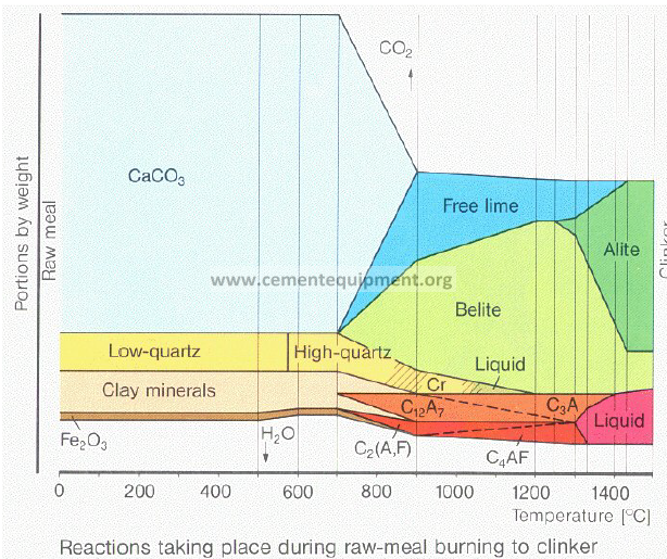
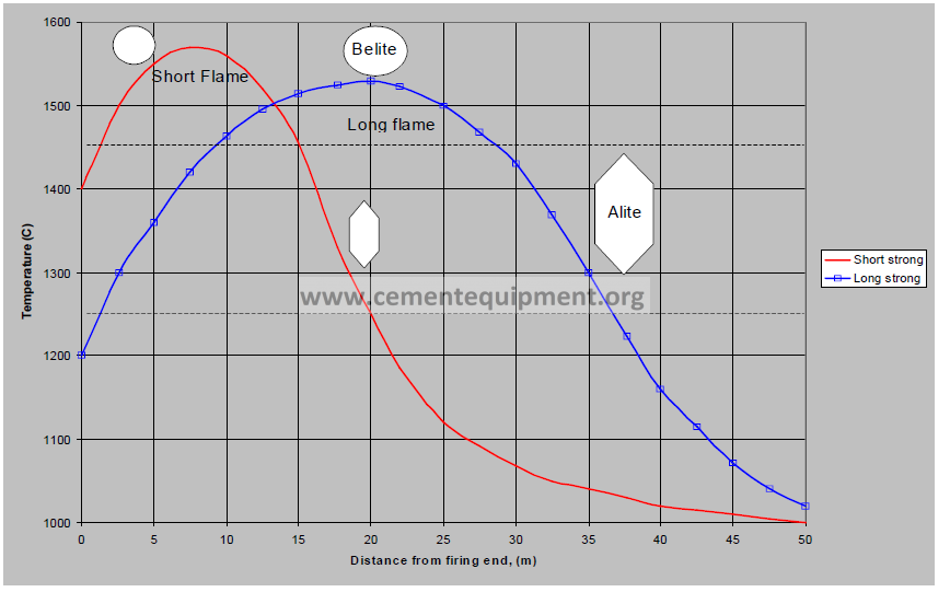
Figure 2: Effect of flame temperature profile on clinker minerals
Burning fuel provides the energy to achieve the temperatures needed for the clinkering
reactions. The purpose of the pyro-processing system is then to facilitate heat transfer
between the hot gases formed by burning the fuel and the clinker material. The burning
zone in the kiln is the most critical section of the pyro-processing system in the
determination of clinker quality in terms of mineralogy and cementicious content.
3. Burner Design
The flame produced in a kiln is a key determinant of clinker quality. An ideal kiln flame
for clinker quality and kiln efficiency should be short and hot to the extent possible
without burning out refractory and without creating an unstable kiln.
The kiln burner introduces fuel and air into a kiln such that the fuel burns and releases
heat to form clinker. The fuel must come into close contact with oxygen in the air, the
combustion reaction must occur efficiently and, finally, the desired heat profile must be
released. At the same time, emissions such as CO, hydrocarbons and NOx must be
minimised, and the flame must not strike the kiln walls and damage refractory.
Burner design is also complicated by the harsh atmosphere inside a kiln. Flame
temperatures are over 2,000ºC and the gases have extremely high dust loads. Thus, the
burner is subjected to heat and abrasion damage.
There are, therefore, two areas than need to be considered in effective burner design:
– Combustion and heat transfer design, to address the chemical reactions and heat
transfer.
– Mechanical design, to ensure the integrity of the design in the harsh kiln
atmosphere.
Combustion and Heat Transfer Design
Every kiln has its own heat transfer needs. A burner that is optimum in one kiln may be
disastrous in another. Effective burner design requires an understanding of the
characteristics of, and the various processes carried out in, the particular kiln.
Fuel Combustion
Traditional fuels are gaseous (natural gas), liquid (oils) or solid (coal and petcoke). In
many cement industries solid fuels are dominant because they are most economical.
Coal is the most commonly used solid fuel and is often supplemented with alternate fuels
such as petcoke. Petcoke has higher CV but usually comes with an excess of sulfur
which can cause buildup problems in the kiln or cyclones. Careful burner design can
allow higher rates of petcoke firing and yield significant savings. Some plants have been
able to increase coke from 40% to 100% because the sulfur is combined into the clinker
and, therefore, does not accumulate in the process.
Natural gas is a convenient fuel. It is clean, easy to handle, and there is no working
capital in stockpiles or tanks. The major drawback with gas is it the fact that its flame
luminosity is much lower than that of oil or solid fuel. Gas flames have low emissivity
and this in turn reduces the amount of radiation heat transfer (Figure 3). While the heat
release profile produced by a typical gas flame is not ideal for clinker formation, efficient
burner design can compensate for this.
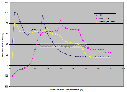
Figure 3: Heat release profile of various burners. Blue line is a typical oil flame and
pink line is typical gas. Yellow line is a gas fired FCT Gyro-Therm burner.
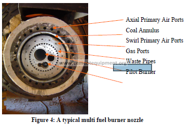
Figure 4: A typical multi fuel burner nozzle
Gas is introduced through a nozzle, typically of multiple ports. The size of the ports is
based on the gas flow and available gas pressure (Figure 4).
It is possible to enhance the heat transfer from a gas flame by using a special nozzle. The
technology utilises an FCT Gyro-Therm nozzle (Figure 5), where the gas exits the nozzle
in a stirring motion that creates a flame with a much higher emissivity resulting in a heat
transfer profile that is more suitable for clinker manufacture. Where gas is the primary
fuel an FCT Gyro-Therm burner provides the best heat release profile.
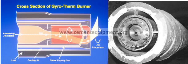
Figure 5: FCT Gyro-Therm gas burner nozzle
Liquid fuels, such as oil, burn by vaporising and then reacting with oxygen. As smaller
droplets vaporise more easily, oil is or atomised when it is introduced into the kiln for
firing.
Oil can be atomised using high pressure or steam. In high pressure (typically 400-600
psig) atomisation the pressure energy of the oil breaks down the oil into fine droplets.
However, as oil flow is reduced, oil pressure and hence atomisation efficiency is reduced.
High pressure atomised oil burners typically have low turndown ratios of around 3:1.
When oil is steam (or air) atomised, the energy for atomisation is provided by the steam.
This makes the spray fineness independent of the oil pumping pressure. Therefore, a
steam atomised oil burner has much greater turndown (e.g.10:1). Furthermore, the
pressures needed to break down the oil are much lower, around 125 psig for the oil and
100 psig for the steam. Steam or air atomisation provides mechanical and electrical
savings at the expense of the cost of steam or air.
Care should be taken when firing waste oils to ensure that solids do not block the nozzle.
Fineness of atomisation is critical to ensure efficient combustion. Where filtration of the
solids is not practical, special nozzles are available for oils with high solids contents.
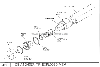
Figure 6: FCT Steam Atomised Oil Sprayer
Solid fuels undergo a similar process to oil during combustion. The volatiles vaporise,
mix with oxygen and then burn. A carbon particle is left, into which oxygen diffuses and
reacts. As this is a surface reaction, surface area is maximised when the fuel particle is
smallest. Typically the residence time in a flame is about 1 second, and a 200 μm particle
takes about 1 second to burn. As such, the maximum desired particle size for a solid fuel
is about 200 μm.
For efficient combustion solid fuels are normally ground to a fineness of 10-15% residue
on a 75 μm (200 mesh) sieve. A coal nozzle is essentially an open annulus (Figure 4).
The key design parameters are the free area and the injection velocity. While there are
basic guidelines for sizing a solid fuel annulus, FCT uses mathematical modelling to
predict solid fuel particle burnout (Figure 7).
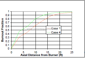
Figure 7: Coal particle burnout depends on particle size
As described above, the proper introduction of fuel is a pre-requisite for efficient burner
design. However, the flame shape also depends heavily on air flows, including primary
air (introduced through the burner) and hot secondary air (the air the flows around the
outside of the burner). The momentum (mass and velocity) of the air streams creates
turbulence and promotes mixing of fuel and oxygen. For each kiln there is an optimum
momentum ratio between the two air streams.
Most of the primary air is axial, but it can also be swirled. Swirled primary air creates
mixing close to the burner nozzle and promotes flame stability. It also makes the flame
wider. Therefore, the ratio of axial and swirl air can be used to control flame shape.
Increasing axial air makes the flame narrower, while increasing swirl air makes the flame
wider.
Secondary air enters the kiln via the cooler and accounts for 85-90% of the air in a
preheater/precalciner kiln. This air is not controlled by the burner, but has a strong
influence on flame shape.
In order to determine the correct burner primary air flows for a kiln, FCT uses physical
modelling techniques (Figure 8). Physical modelling allows the visualisation of air flow
patterns in a kiln and the corresponding flame shape. Physical modelling results provide
critical burner information such as primary air, optimum excess oxygen, burner insertion
distance and burner angle.
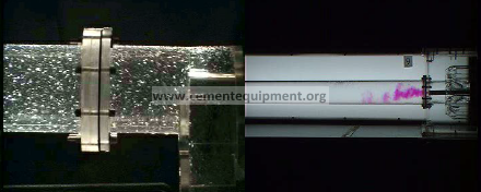
Figure 8: Physical modelling techniques. The left image shows a water bead model
illustrating air flow patterns. Right is an acid/alkali simulation of flame shape.
Mechanical Considerations
The kiln atmosphere is harsh, with flame temperatures exceeding 2,000°C and extreme
dust loads in the kiln gases. Dust can also settle and build up on the burner body and
nozzle, thus restricting the flow of fuel and air. These factors have a deleterious affect on
flame shape and control.
A simple design is best. The burner body should be of robust construction with
mechanisms for alignment of the various pipes. Internal surfaces should be smooth, and
areas that are subject to wear, such as the coal/petcoke entry, should be lined with a
suitable wear resistant material.
The burner nozzle is the most critical area of the burner as this affects the combustion
performance. Special high temperature alloys are used at the face plate, with machined
ports for air and gas to avoid distortion. Solid fuel channels are open ended as are the
pipes that are used for alternative fuels (Figure 4).
The design of the burner also allows for expansion and contraction during kiln warm up
and shutdown, and any welds are kept distant from the surfaces exposed to heat.
4. Alternative Fuels
There are numerous types of alternative fuel. Some common ones of interest to the
cement industry are:
-Petroleum Coke,
– Waste Tyres,
-Rice husk,
– Liquid Waste,
– Sawdust,
– Wood,
– Municipal Waste,
– Sewage Sludge, and
– Carbon anodes.
Alternative fuels are used because they are cheaper to use than the fossil fuels. There is
also an environmental benefit in that high value fossil fuels are conserved, thus saving the
corresponding CO2 emissions. The maximum benefit is achieved when the alternative
fuel is used with minimal preparation. Thus, an alternative fuel may consist of large and
irregular shaped particles, have variable calorific value, be of variable chemical content,
and contain chemicals that may have a deleterious effect on kiln operation.
Irregular shaped and sized particles: Solid wastes are much larger than the maximum
particle size for optimum firing, i.e. 200μm. Liquid wastes have solid particles in them,
which makes atomisation difficult. Alternative fuels are prone to fall onto the clinker and
affect flame temperature and, hence, clinker formation.
Variable Calorific Value: This means that the energy supplied to the kiln will be
variable. As such, flame temperature and, hence, heat transfer to the clinker will vary
and affect clinker formation.
Variable Chemical Content: This will affect the clinker composition as well as
crystalline structure. A change in the raw mix may be required.
Undesirable Chemicals: Many alternative fuels are high in various undesirable
chemicals. Some chemicals contain alkalis, chlorine and sulfur, which can upset kiln
cycles and lead to deposits. Sometimes a by-pass system is required to purge these.
Solid wastes are introduced into the kiln via an open pipe. Liquid wastes are sprayed
using a large nozzle to avoid blockage of the small holes needed for fine sprays. The
principles for primary air design and flame shape described above can still be applied but
it is inevitable that some of the alternative fuel will burn on the clinker bed, and the flame
temperature may vary. These factors have a significant, generally negative, impact on
heat transfer and clinker mineralogy.
This is one of the big challenges in using alternative fuels. The variable and generally
poorer combustion characteristics of alternative fuels make it much more difficult to
achieve a good kiln flame for clinker production at higher rates of substitution. The
alternative fuel may have a lower calorific value, making clinkering temperatures
difficult to achieve, or burn rates may be slow and unburned fuel may finish on the
clinker bed. Other problems may arise from the higher percentages of chlorine or sulfur
that give rise to build up and kiln instability.
Thus, kiln burner design is even more critical with alternative fuels. The burner must
exhibit excellent fuel/air mixing characteristics and allow for adjustment of the
conventional fuel to cover for any variations in the characteristics of the alternative fuels.
Continuous knowledge of clinker quality is also important so that, in the event that
clinker quality deteriorates, the burner can be adjusted to compensate. The timeliness of
this information will allow clinker quality to be maintained continuously and the amount
of alternative fuel used to be maximised.
5. On-Line Quality Control
As discussed above, the relatively poor combustion characteristics of alternative fuels
make burner design critical to maximise the amount of alternative fuel fired. However,
as the degree of substitution increases, the point may be reached where clinkering reactions do not go to completion, or there may be some minor elements present that
cause an unknown change to the clinker mineralogy. Generally, the kiln operator is
ignorant of these when using standard clinker analysis procedures such as XRF and
Bogue to calculate mineralogy. Therefore, continuous monitoring of clinker quality is
the best way to control alternative fuel firing.
It is well known that the performance of a cement plant, as well as the quality of the final
cement product, is governed largely by the mineralogy of materials, and not just by the
elemental composition. Burnability of raw feed, grindability of raw materials and
clinker, strength development, and cement setting times are examples of important
cement plant parameters that are controlled by mineralogy, and not by chemical
composition. Even before mineral analysis was prevalent, cement chemists measured
chemical compositions, using XRF for example, and then attempted to calculate minerals
using the Bogue equations.
It is the clinker minerals C3A, C4AF, C2S and C3S (that are approximated by the Bogue
formula) that need to be monitored to ensure quality.
X-ray Diffraction
Perhaps the most common technique for measuring mineral content is X-ray diffraction
(XRD). The technique involves firing an X-ray beam onto a sample and then measuring
its diffraction pattern.
When X-rays are fired onto a crystalline material they diffract off each layer of the
crystalline lattice. At certain angles the diffracted X-rays will be in phase and the signal
will be very strong (Figure 9). At other angles they are out of phase and the X-rays
cancel each other. The angle at which the diffracted rays are in phase is related to the
distance between the lattice plane, and this is characteristic for a particular mineral. For
example, the mineral tri-calcium silicate (C3S) has a characteristic angle.
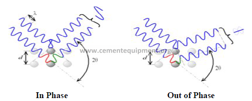
Figure 9: X-ray diffraction (XRD) from a crystalline material.
When a composite material such as cement or clinker is analysed by XRD, a range of
diffracted peaks will occur. The angle of each peak can be used to identify the mineral
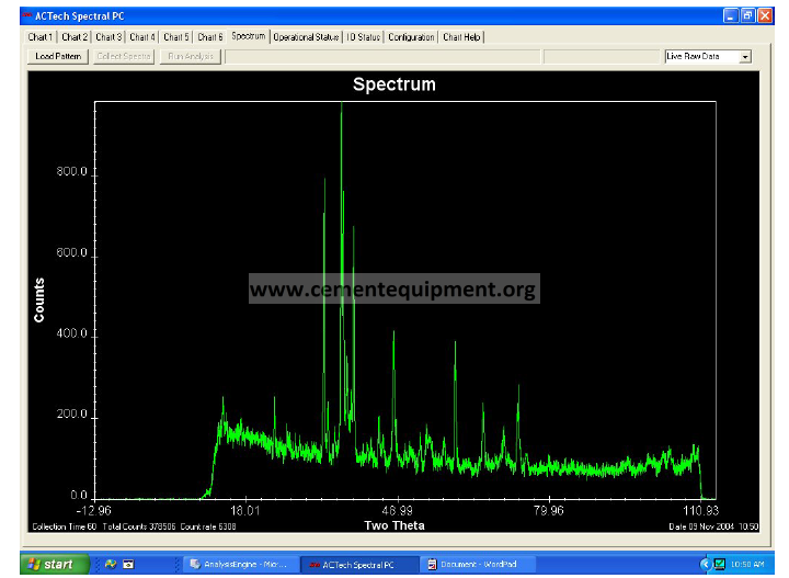
while the intensity of the peak will indicate the relative amount present. Figure 10 shows
a pattern for a typical cement type.
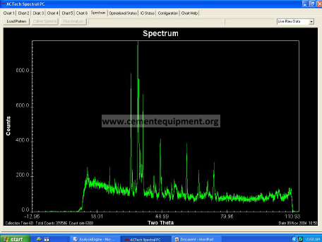
Figure 10: XRD pattern of cement. Each compound contributes one or more peaks
to the pattern.
There are, of course, many complicating factors. In order to arrive at the profile in the
figure above and convert it into mineral composition, industrial machines use powerful
software and the Reitveld analytical method.
Continuous On-Stream Mineral Analysis
Until recently most XRD analysers were laboratory based. A sample was collected,
prepared and analysed. From the pattern, the composition of a small sample was
determined. The fastest laboratory analysers require several minutes to analyse the data
and provide the results.
FCT provides a field XRD analyser, the Continuous On Stream Mineral Analyser or
COSMA, which analyses minerals continuously. This instrument has a curved X-ray
detector that picks up the complete X-ray pattern continuously (Figure 11). It is this
unique feature that differentiates COSMA from other instruments, and allows the
monitoring of minerals. A typical process flow diagram of COSMA on clinker is given
in Figure 12 and a typical output from the machine is provided in Figure 13.
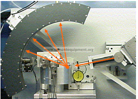
Figure 11: X-rays are diffracted continuously from a moving stream to COSMA’s
patented curved detector.
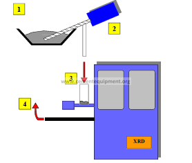
Figure 12: Typical process flowsheet of a COSMA installation showing sample
acquisition.
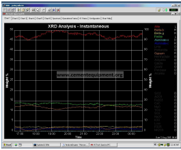
Figure 13: Typical display of clinker minerals from COSMA
The benefits of using continuous monitoring compared to conventional laboratory based
XRD techniques include:
-extremely rapid turn-around times for analyses,
– improved accuracy, and
– lower limits of detection for the phases.
COSMA analyses approximately 600g of sample per minute. An analysis is provided
each minute, based on data averaged over the preceding 10 minutes to reduce variations.
Software is adjustable to suit the particular application.
As X-rays used in XRD instruments do not penetrate the surface of the powder more than
a few microns, laboratory instruments only analyse a very small amount of the material
sample. On the other hand, continuous XRD analyses significantly more material
because a fresh stream of material is continuously passing under the X-rays. COSMA
analyses several thousand times more material than a laboratory unit in a given time
period.
Such frequent analysis allows trending of results and provides the ability to control
processes ‘on-line’. Figure 14 shows how the machine monitors free lime, alite and
belite content. These are key components that determine kiln operation. In this example
there was a free lime excursion that was caused by a cool kiln, as alite reduced and belite
increased. If, however, free lime had increased without a corresponding decrease in alite,
then the excursion would have been due to a raw mix proportioning variation.
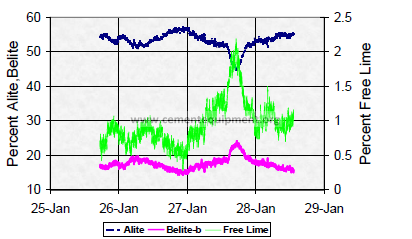
Figure 14: Free lime, generated by a cold kiln, is monitored by COSMA
6. Conclusions
The mineralogical processes that lead to clinker formation depend greatly on time and
temperature. The final reactions that determine clinker and cement properties occur in
the hottest parts of the rotary kiln. As such, the fuel burner must be designed to ensure
that the correct temperature profile is attained. This is possible by applying fundamental
knowledge of fuel combustion and flame simulation techniques. The burner can thus be
optimised for clinker formation.
Burning alterative fuels causes complications because they are highly inconsistent in
form and composition. Some alternative fuel particles are too large for efficient
combustion, and these may burn on the clinker bed. The operator must compensate for
this by having excellent control and flame shaping ability. When and how these changes
are made can only really be determined by clinker quality.
Continuous knowledge of the clinker phases provides immediate information to the kiln
operator to act upon. In the event that heat transfer is reduced (e.g. low free lime and
alite content) the operator can increase the rate of fuel.
COSMA continuously measures the quality of clinker. The machine takes a solid stream
and analyses it using standard X-ray diffraction techniques, but in a continuous manner.
This provides a direct measurement of mineralogical content.
Due to the nature of alternative fuels, it is likely that by increasing their firing rate a point
will be reached when heat transfer and clinker quality is diminished, even with the best
designed burner. A continuous knowledge of clinker quality will immediately indicate
when this point is reached. COSMA provides this intelligence. Using data from
COSMA the kiln operator can adjust burner parameters, kiln parameters and raw mix as
necessary.
A combination of COSMA and optimised burner, therefore, creates a powerful tool to
optimise alternative fuel firing, while maintaining clinker quality.